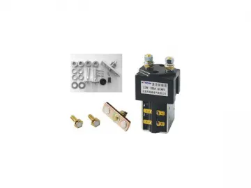
YF 100A DC contactor
Application:
YF100A series DC contactors are suitable for the battery or the rectificationpower, using for handling drawing, the pump motor and other electronicvehicles. At the same time it has been widely used in communications power, UPSand other electronic control system
Brief Technical Data:
| Number | Type and parameter | Coil and rated volt of contact circuit(v) | ||||||||
| 12 | 24 | 3 0 | 36 | 40 | 48 | 60 | 72 | 8 80 | ||
| 1 | Coil power dissipation <15(w), Max.coil current(A) | 0.98 | 0.58 | 0.45 | 0.35 | 0.32 | 0.28 | 0.25 | 0.2 | 0.18 |
| 2 | main rated load current of contact circuitA) | Resistive load:て=1ms 100A Max.Rated working current of contact circuit for 4le, 5 seconds. | ||||||||
| 3 | voltage | 50Hz 1000V AC 1min | ||||||||
| 4 | Operating time | Pickup(contact makes):≯30ms ,release(contact breaks):≯30ms | ||||||||
| 5 | Action characteristic | Release(contact breaks):≯30%Us,≮5%Us Pickup(contact) | ||||||||
| 6 | Mechanical life | 1 million times | ||||||||
| 7 | Electric life | Resistive load:50000times, inductive load(DC-5):60%le for Resistive load,10000times | ||||||||
| Notice: 1 . Specifications subject to change as the custom request 2 . Coil voltage in above 48V with permanent magnet blowouts | ||||||||||
Environmental condition:
1. Ambient temperature:-25~ 40℃
2. Altitude range:0~2000m
3. Max.relative humidity90% at 25℃
4. Vibration:10~50Hz,10m/s2
5. Shock:30m/s2
6. Installation method:anywhere
7. Voltage fluctuating:0.7~1.1Ue
8. Duty:8h continuous
Configurational mounting diagram:
Circuit diagram:
Nomination(nomogram):
Links:https://www.globefindpro.com/products/102452.html
-
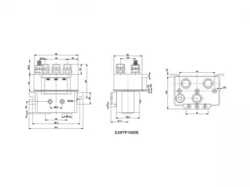 YF 100DE DC contactor for electric winch
-
 MOS (Mannan Oligosaccharide)
-
 Yeast Vitamin B Complex Powder / Flakes
-
 Chromium-enriched Yeast
-
 Nutritional Yeast Powder
-
 Selenium Yeast
-
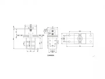 YF 500A DC contactor
-
 YF2, YF2P DC contactor
-
 YF3, YF3P DC contactor
-
 YFH 400A-2T DC contactor
-
 YFT 50A DC contactor
-
 Yeast Beta Glucan
