Two Stage Air Compressor, Oil-injected Rotary Screw Compressor
Features High efficient and energy saving screw air-end
The compressor applies a large rotor, which works at a low rotation rate. The precision machining process grants a high rotor profile accuracy, which allows for minimized vibrations and noise. It also improves sealing during the air compressor’s operation.
There are two independent compressing units in one air-end. Undertaken by two units together, the combined system grants lower loads for each bearing than a single unit. This allows for better bearings durability.
Lubricating oil is separately injected into the air compression chamber and the bearings. Then bearings are then injected with clean lubricating oil for better reliability. As a result, the air-end is granted lower compression ratios, lower leakage and better volumetric efficiency.
High efficient rotor
Direct drive large rotor works at low rotation rate, providing good efficiency, low energy cost, and lower inherent leakage;
High efficiency, low noise & vibration;
Bearings with good efficiency are applied, such as cylindrical roller bearing, angular contact ball bearings, etc.
Bearing lifespan ≥ 100,000 hours;
Highly accurate rotor profile grants high performance and reliability.
Premium high efficient motor
The motor applies heavy-duty SKY bearing with port for lubricating oil injection on the housing, which is convenient for maintenance;
IP55 water and dust proof, grants better durability.
Optimized structure
Cold and hot air are separately stored in different chambers, which offers better cooling performances. This grants a longer service life for the air compressor.
Removable enclosure with premium flame retardant & sound-proof sponge, which grants a lower noise during operation. This also makes installation and maintenance very convenient.
Oil separator installed together with after cooler
After cooler is installed next to the oil separator, ensuring reduced installation space & pipeline connection, and high oil separating efficiency. Atomized oil injection inter-stage cooling design
Atomized oil gets injected for inter-stage cooling and lubricating. this omits the inter-stage cooler and decreases pressure loss. This also grants better cooling efficiency, lubrication performance, lower energy cost, and lower maintenance cost. Oil stop & vent combined valve
The oil stop & vent combined valve structure ensures the compressor is running at a light load. This decreases the impact on the power grid and increases motor durability.
Helps avoid oil leakage and start-up failure in low-temperature conditions.
Simple structure, convenient for connection, stable & reliable.
Energy-saving air inlet control system
The air compressor features an up-to-date control system and an integrated design combined with air inlet and outlet function, greatly reducing pipeline connection.
Air inlet control system applies unidirectional valve, which turns off automatically when the compressor shuts down or if it stops air supply suddenly. This is to avoid compressed air return and oil-leakage.
Along with an intelligent control system and pressure sensor, the air inlet valve offers airflow on/off control, continuously variable pressure control (60%-100%), along with delay start/stop control.
High quality wear parts
Air filtering element: with special nano-coating applied, airflow goes through the filtering element without the direction being changed. This lessens pressure loss, and grants better filtering accuracy.
Oil separating element: coalescing oil separating element and oil return device ensure that the oil content of outlet air is ≤ 2PPM.
Technical Parameters
Note:

The compressor applies a large rotor, which works at a low rotation rate. The precision machining process grants a high rotor profile accuracy, which allows for minimized vibrations and noise. It also improves sealing during the air compressor’s operation.
There are two independent compressing units in one air-end. Undertaken by two units together, the combined system grants lower loads for each bearing than a single unit. This allows for better bearings durability.
Lubricating oil is separately injected into the air compression chamber and the bearings. Then bearings are then injected with clean lubricating oil for better reliability. As a result, the air-end is granted lower compression ratios, lower leakage and better volumetric efficiency.
High efficient rotor
Direct drive large rotor works at low rotation rate, providing good efficiency, low energy cost, and lower inherent leakage;
High efficiency, low noise & vibration;
Bearings with good efficiency are applied, such as cylindrical roller bearing, angular contact ball bearings, etc.
Bearing lifespan ≥ 100,000 hours;
Highly accurate rotor profile grants high performance and reliability.
Premium high efficient motor
The motor applies heavy-duty SKY bearing with port for lubricating oil injection on the housing, which is convenient for maintenance;
IP55 water and dust proof, grants better durability.
Optimized structure
Cold and hot air are separately stored in different chambers, which offers better cooling performances. This grants a longer service life for the air compressor.
Removable enclosure with premium flame retardant & sound-proof sponge, which grants a lower noise during operation. This also makes installation and maintenance very convenient.
Oil separator installed together with after cooler
After cooler is installed next to the oil separator, ensuring reduced installation space & pipeline connection, and high oil separating efficiency. Atomized oil injection inter-stage cooling design
Atomized oil gets injected for inter-stage cooling and lubricating. this omits the inter-stage cooler and decreases pressure loss. This also grants better cooling efficiency, lubrication performance, lower energy cost, and lower maintenance cost. Oil stop & vent combined valve
The oil stop & vent combined valve structure ensures the compressor is running at a light load. This decreases the impact on the power grid and increases motor durability.
Helps avoid oil leakage and start-up failure in low-temperature conditions.
Simple structure, convenient for connection, stable & reliable.
Energy-saving air inlet control system
The air compressor features an up-to-date control system and an integrated design combined with air inlet and outlet function, greatly reducing pipeline connection.
Air inlet control system applies unidirectional valve, which turns off automatically when the compressor shuts down or if it stops air supply suddenly. This is to avoid compressed air return and oil-leakage.
Along with an intelligent control system and pressure sensor, the air inlet valve offers airflow on/off control, continuously variable pressure control (60%-100%), along with delay start/stop control.
High quality wear parts
Air filtering element: with special nano-coating applied, airflow goes through the filtering element without the direction being changed. This lessens pressure loss, and grants better filtering accuracy.
Oil separating element: coalescing oil separating element and oil return device ensure that the oil content of outlet air is ≤ 2PPM.
Technical Parameters
| Model | Power | Pressure Mpa | Air Displacement m3/min | Noise Level | Air Outlet Size | Dimensions mm LXBXH | Weight | Oil Volume L | ||
| KW | dB(A) | ('') | kg | |||||||
| JF-20AⅡ | 15 | 0.7 | 2.9 | 64±2 | G1½'' | 1620 | 1000 | 1320 | 680 | 30 |
| 0.8 | 2.8 | |||||||||
| 1 | 2.4 | |||||||||
| JF-25AⅡ | 18.5 | 0.7 | 3.6 | 65±2 | G1½'' | 1620 | 1000 | 1320 | 720 | 30 |
| 0.8 | 3.4 | |||||||||
| 1 | 2.9 | |||||||||
| 1.3 | 2.5 | |||||||||
| JF-30AⅡ | 22 | 0.7 | 4.2 | 66±2 | G1½'' | 1620 | 1000 | 1320 | 800 | 30 |
| 0.8 | 4.1 | |||||||||
| 1 | 3.5 | |||||||||
| 1.3 | 3.2 | |||||||||
| JF-40AⅡ | 30 | 0.7 | 6.2 | 66±2 | G2'' | 1620 | 1000 | 1320 | 920 | 30 |
| 0.8 | 6 | |||||||||
| 1 | 4.9 | |||||||||
| 1.3 | 4.2 | |||||||||
| JF-50AⅡ | 37 | 0.7 | 7.2 | 68±2 | G2'' | 2000 | 1250 | 1670 | 1000 | 62 |
| 0.8 | 7 | |||||||||
| 1 | 6.3 | |||||||||
| 1.3 | 5.4 | |||||||||
| JF-60AⅡ | 45 | 0.7 | 9.8 | 70±2 | G2'' | 2000 | 1250 | 1670 | 1500 | 62 |
| 0.8 | 9.6 | |||||||||
| 1 | 7.8 | |||||||||
| 1.3 | 6.5 | |||||||||
| JF-75AⅡ | 55 | 0.7 | 12.6 | 69±2 | G2'' | 2000 | 1250 | 1670 | 1600 | 62 |
| 0.8 | 12.3 | |||||||||
| 1 | 9.6 | |||||||||
| 1.3 | 8.6 | |||||||||
| JF-100AⅡ | 75 | 0.7 | 17 | 70±2 | G2'' | 2700 | 1600 | 1840 | 1750 | 76 |
| 0.8 | 16.5 | |||||||||
| 10 | 12.5 | |||||||||
| 1.3 | 11.2 | |||||||||
| JF-120AⅡ | 90 | 0.7 | 19.8 | 72±2 | G1½'' | 2700 | 1600 | 1840 | 2600 | 76 |
| 0.8 | 19.2 | |||||||||
| 1 | 16.8 | |||||||||
| 1.3 | 14.5 | |||||||||
| Model | Power | Pressure Mpa | Air Displacement m3/min | Noise Level | Air Outlet Size | Dimensions mm LXWXH | Weight | Oil Volume L | ||
| KW | dB(A) | ('') | kg | |||||||
| JF-150AⅡ | 110 | 0.7 | 24 | 73±2 | G1½'' | 2700 | 1600 | 1840 | 2760 | 76 |
| 0.8 | 23.2 | |||||||||
| 1 | 19.7 | |||||||||
| 1.3 | 17.6 | |||||||||
| JF-175AⅡ | 132 | 0.7 | 28.2 | 75±2 | G3''/DN80 | 3400 | 1700 | 1950 | 3300 | 90 |
| 0.8 | 27.7 | |||||||||
| 1 | 23.5 | |||||||||
| 1.3 | 19.8 | |||||||||
| JF-200AⅡ | 160 | 0.7 | 34.5 | 75±2 | G3''/DN80 | 3400 | 1700 | 1950 | 3400 | 90 |
| 0.8 | 33.6 | |||||||||
| 1 | 30 | |||||||||
| 1.3 | 23.8 | |||||||||
| JF-250AⅡ | 185 | 0.7 | 41 | 76±2 | G3''/DN80 | 3700 | 1980 | 2150 | 4200 | 125 |
| 0.8 | 38.6 | |||||||||
| 1 | 33 | |||||||||
| 1.3 | 28.6 | |||||||||
| JF-270AⅡ | 200 | 0.7 | 44.5 | 76±2 | DN100 | 3700 | 1980 | 2150 | 4300 | 125 |
| 0.8 | 43.2 | |||||||||
| 1 | 38.5 | |||||||||
| 1.3 | 33 | |||||||||
| JF-300AⅡ | 220 | 0.7 | 48.6 | 79±2 | DN100 | 3700 | 1980 | 2150 | 4400 | 125 |
| 0.8 | 47 | |||||||||
| 1 | 41 | |||||||||
| 1.3 | 38 | |||||||||
| JF-340AⅡ | 255 | 0.7 | 55 | 78±2 | DN125 | 4100 | 2100 | 2150 | 190 | |
| 0.8 | 54 | |||||||||
| 1 | 46 | |||||||||
| 1.3 | 40 | |||||||||
| JF-380AⅡ | 285 | 0.8 | 60 | 80±2 | DN125 | 4100 | 2100 | 2150 | 190 | |
| 1 | 52 | |||||||||
| 1.3 | 45 | |||||||||
| JF-430AⅡ | 315 | 0.8 | 67 | 80±2 | DN125 | 4100 | 2100 | 2150 | 200 | |
| 1 | 63 | |||||||||
| 1.3 | 51 | |||||||||
Types listed above all apply 380V/50HZ power source, four-pole motor; Start-up: frequency variable or Y-△; All types using 60HZ power source are unlisted.

Scan QR to Read
Links:https://www.globefindpro.com/products/10380.html
Links:https://www.globefindpro.com/products/10380.html
Recommended Products
-
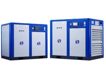 Oil-injected Rotary Screw Compressor, Low Pressure Series
-
 Air Compressor Filter
-
 RENAULT Charge Air Cooler
-
 Piston Compressor, Variable Speed Air Compressor
-
 SCANIA Charge Air Cooler
-
 Oil-injected Rotary Screw Compressor, with Permanent Magnet Drive
-
 VOLVO Oil Cooler
-
 Piston Compressor, Power Series
-
 MERCEDES Charge Air Cooler
-
 Oil Free Screw Air Compressor (Water Lubricating)
-
 Oil-injected Rotary Screw Compressor, with Belt Transmission
-
 NISSAN Charge Air Cooler
Hot Products
