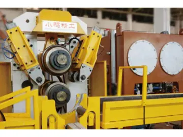
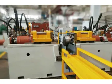
Rim Roller Machine
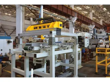
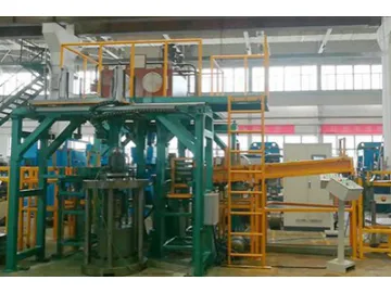
The rim roller machine is intended for rim processing. Rim rolling usually involves three processes, each of which requires a rim roller machine consisting of the main machine, hydraulic system, PLC control system, loading and unloading device and rim roller tooling.
2nd roll forming
3rd roll forming
4th roll forming for non-skid pattern
Features The easy-to-disassemble design, with an optional fast die-changing mechanism, helps to effectively control the changing time within 30min. Both small and large wheel rim production lines use 3 rim roller machines for different roll forming processes. The 3 roller machines share one set of automatic loading and unloading mechanisms to achieve automatic operation. With a 3 process and 4-station design, it allows for simultaneous loading and unloading in all 3 processes to save time and improve productivity. The loading and unloading mechanism is connected to the main machine in a split design. The manually operated production line can be disassembled for changeover between manual operation and automatic operation. The roll forming die can be customized to be symmetric or asymmetric according to customer machining requirements. Upper and lower spindles are hydraulic driven. The speed of upper and lower forming rolls can be automatically adjusted during the roll forming process. The spindle is adjustable in dip angle and axial direction to ensure each part of the roll forming die surface features consistent stress and ensures the processing accuracy. Space between upper and lower spindles can be adjusted, as well as the feeding speed. The stroke of side guide roller is also adjustable. Technical specs
| No. | Description | Data | |||
| 1 | Model | GX-23/300 | GX-45/600 | GX-48/800 | |
| 2 | Roll forming force | 230kN | 400kN | 500kN | |
| 3 | Motor power of hydraulic system | 62.5Kw | 82.5Kw | 165KW | |
| 4 | Die length on spindle | 350mm | 670mm | 900mm | |
| 5 | Spindle speed | 220r/min | 200r/min | 200r/min | |
| 6 | Spindle material and size | 40Cr, 140mm | 40Cr, 200mm | 40Cr, 220mm | |
| 7 | Space between upper and lower spindle | 240~380mm | 340~480 | 380~520 | |
| 8 | Lower spindle stroke | 140mm | 140mm | 140mm | |
| 9 | Feeding speed range of lower spindle | 2~10mm/s | 2~10mm/s | 2~10mm/s | |
| 10 | Adjustable dip angle of lower spindle | -0.35 ° ~0.17 ° | ±0.35° | ±0.35° | |
| 11 | Side guide roller (linear) | Stroke | 100mm | 140mm | 160mm |
| Adjustment | 50mm | 50mm | 50mm | ||
| 12 | Max. Diameter of guide roller | 200mm | 220mm | 240mm | |
| 13 | Rated input voltage | 380V | 380V | 380V | |
| 14 | Rated input power | 62.5kW | 82.5kW | 165kW | |
| 15 | Power cord section (copper) | Single core, 70m2 (3+2) | Single core, 90 m2 (3+2) | Single core, 180 m2 (3+2) | |
| 16 | Hydraulic cooling water consumption | 2000L /h | 3000L /h | 4000L /h | |

Scan QR to Read
Links:https://www.globefindpro.com/products/16802.html
Links:https://www.globefindpro.com/products/16802.html
Recommended Products
-
 2KG Mini Top Load Washing Machine
-
 Run-out Measuring Machine
-
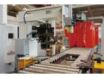
 Trimming-Planishing-End Cutting Unit
-
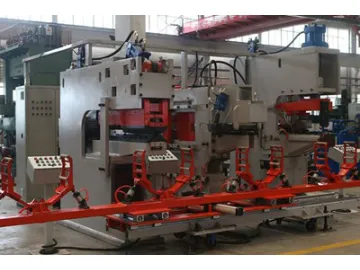
 Rim Flare Press
-
 CBB3256-1 Neoprene Bottle Holder
-
 Outfeed Conveyor
-
 Rim Expander Press
-
 CBB2666-1 Multifunctional Large Capacity Tool Backpack, 57.1*36.8*28cm Electric Tool Bag
-
 CBB2051-1 Functional Multi Pockets Tool Bag, 30x25x15CM Detachable Polyester Tool Pouch
-
 CBB5866-1 Pink Cotton Buffalo Check Apron
-
 CBB2388-1 Polyester Pen Bag, Stationery Storage Bag
-
 CBB1668-1 Polyester BBQ Kit Bag
Hot Products