Linear Actuators & Electric Motion Control Products Manufacturer
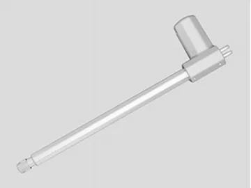
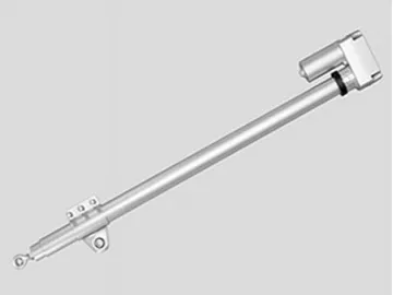
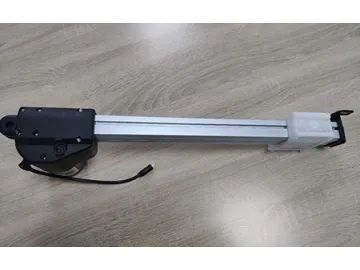
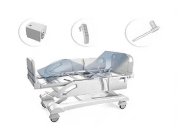
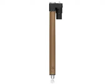
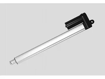
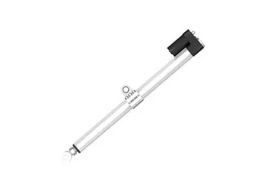
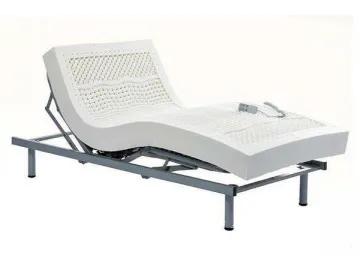
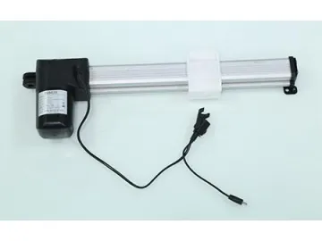
The U2 model medical linear actuator is a low-noise, heavy duty motion linear actuator used for hospital beds, dental chairs, and other health care beds. Due to the metal gear box, its max pushing force is up to 8000N, which meets medical equipment requirements.
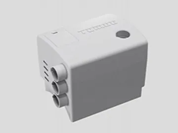
The front and rear ends of the U2 model motion linear actuator is made of ADC12 aluminum material, which offers a better durability than the . The sealing elements are surrounded by rubber material to ensure the waterproof performance, and users can choose different brake and overload protection types in customization services. To ensure compatibility with the control box, the U2 medical linear actuator’s outlet is different than the .
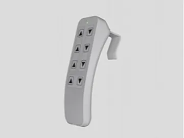
This type of linear actuator is equipped with a power adapter and manual controller, and one control box is capable of simultaneous control of 2 or 3 actuators. To meet customer requirements, this linear actuator can also be equipped with a power box in the event of power outages.
ParametersVoltage:12/24V DC
Max load capacity:8000N(push), 4000N(pull)
No-load velocity:5~39.5mm/s
Full-load velocity:2.5~23.4mm/s
Minimum installation distance: s + 163mm
Noise level:less than 52dB
Option Hall sensor
Features
The linear actuator features a small size, large maximum load capacity, low weight, low noise and excellent self-locking performance.
It is equipped with a built-in limit switch. The motor will automatically turn off at the end of each stroke.
The linear actuator uses a metal gearbox and features a long service life.
This product is designed with an exceptionally durable structure.
It carries out a variety of functions, including lift, drop, tilt, and rotate.
A manual controller and power source is optional.
This linear actuator is widely used in medical beds, electric beds, massage chairs and other motorized furniture.
Appearance and size
Curve graph
① Load VS Curent; ② Current (A); ③ Load (N); ④ Load VS Speed; ⑤ Speed (mm/s)
Code of Parameters
| code | Rated laod(N) | Rated current(A) | Rated speed(mm/s) | ||
| Push | Pull | No-load(32VDC) | Full-load(24VDC) | ||
| Standard motor (2600RPM) | |||||
| A | 8000 | 4000 | 4.2 | 5 | 2.41 |
| B | 6000 | 4000 | 3.7 | 6 | 2.63 |
| C | 5000 | 4000 | 3.2 | 8 | 2.88 |
| D | 3500 | 3500 | 2.6 | 11.9 | 3.07 |
| E | 2500 | 2500 | 2.1 | 15.9 | 3.5 |
| F | 2000 | 2000 | 1.7 | 21.4 | 3.38 |
| G | 1000 | 1000 | 1.3 | 32.1 | 3.45 |
| High Speed Motor(3400RPM) | |||||
| H | 8000 | 4000 | 5 | 6.7 | 3.3 |
| I | 6000 | 4000 | 4.3 | 7.6 | 4.1 |
| J | 5000 | 4000 | 4.3 | 10.1 | 5.4 |
| K | 3500 | 3500 | 4.7 | 15.1 | 7.9 |
| L | 2500 | 2500 | 4.2 | 20.2 | 11.1 |
| M | 2000 | 2000 | 4.1 | 27.1 | 14.9 |
| N | 1000 | 1000 | 3.1 | 39.5 | 23.4 |
Comment: when the voltage changes from 24V to 12V, the current will be doubled.
Customization parameter
1=12V
2=24V(standard)
1=0°/180°
2 = 90°
3=30°
4=60°
1=Plastic clevis, slot 6.2mm, hole Φ10.2mm
2=Aluminium alloy clevis, slot 8.2mm, hole Φ12.2mm
3=Aluminium alloy clevis, slot 10.2mm, hole Φ10.2mm
4=Aluminium alloy clevis, slot 10.2mm, hole Φ12.2mm C=customization
1=Width 26mm, hole Φ10.2mm
2=Width 26mm, hole Φ12.2mm
3=Width 32mm, hole Φ10.2mm with plastic cap
4=Width 32mm, hole Φ12.2mm with plastic cap
5 =Plastic clevis, width 32mm, slot 8.2mm, hole Φ10.2mm
6 =Plastic clevis, width 32mm, slot 8.2mm, hole Φ12.2mm
7=Aluminium alloy clevis, width 26mm, slot 6.2mm, hole Φ10.2mm
8=Aluminium alloy clevis, width 26mm, slot 6.2mm, hole Φ12.2mm
9=Aluminium alloy clevis+vinyl sleeve, width 26mm, slot 6.2mm, hole Φ10.2mm
C=customization
1=Black
2=Ivory white
C=customization
1=IP42
2=IP54
3=IP65
4=IP66
5=Without shell
1=no(standard)
2=safe standby screw
3=only push
4=safe standby screw, only push
1=Switches in both end off to stop
2=Switches in both end off to output signal
3=Switches in both end off to stop and a third one off to output signal
4=Switches in both end and a third one off to output signal
C=customization
1=no
2=single Hall sensor
3=Dual Hall sensor
4=reed sensor
1=no
3=One four-and-a-half-cycle torsional spring
2=One three-cycle torsional spring
4=motor brake
1=Tined leads
2= 01 Pin
3=Din 4 pin, 90°
4=Din 5 pin, 90°
5=Din 6 pin, 90°
C=customization
1=0.5m
2=1m
3=1m
4=2m
5=3m
C=customization
1=straight
2=coiled
Links:https://www.globefindpro.com/products/25037.html
-
 Linear Actuators & Electric Motion Control Products Manufacturer
-
 Linear Actuators & Electric Motion Control Products Manufacturer
-
 Linear Actuators & Electric Motion Control Products Manufacturer
-
 Linear Actuators & Electric Motion Control Products Manufacturer
-
 Linear Actuators & Electric Motion Control Products Manufacturer
-
 Linear Actuators & Electric Motion Control Products Manufacturer
-
 Linear Actuators & Electric Motion Control Products Manufacturer
-
 Linear Actuators & Electric Motion Control Products Manufacturer
-
 Linear Actuators & Electric Motion Control Products Manufacturer
-
 Linear Actuators & Electric Motion Control Products Manufacturer
-
 Linear Actuators & Electric Motion Control Products Manufacturer
-
 Linear Actuators & Electric Motion Control Products Manufacturer
