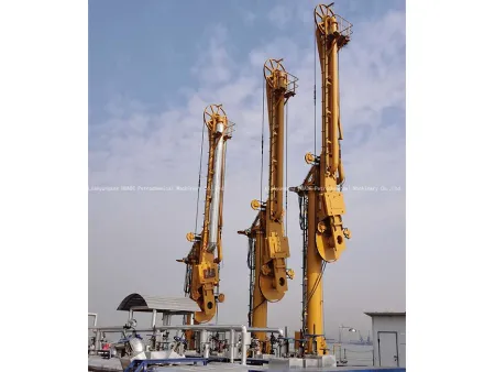
Marine Loading Arm (Hydraulic Operation)
Operating method: hydraulically operated
Supporting structure: independent support, single or double arm
The marine loading arm allows for safe transportation of fluids between the terminal pipeline and the vessel’s pipeline. During the process of fluid transfer, the design of the loading arm allows it to accommodate the drift and movement of the tanker or ship within its predetermined range without damaging the equipment. In order to prevent drifting past the design range, a position monitoring system triggers audible and visual warnings; for added protection, an emergency release system can be installed. The emergency release system is triggered when the tanker exceeds the design range, effectively protecting the loading arm and the pipeline from an accidental damage. Once the emergency disengagement system is activated, the valves at both ends separate and close rapidly, ensuring minimal material leakage.
Links:https://www.globefindpro.com/products/3209.html
-
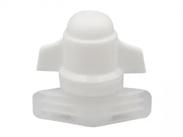 Screw On Spout, LW092
-
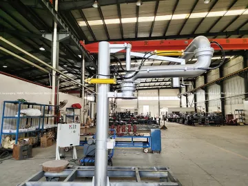 Automatic Loading Arm
-
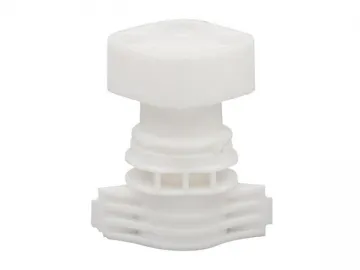 Screw On Spout, LW090
-
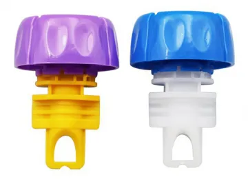 Screw On Spout, LW055C
-
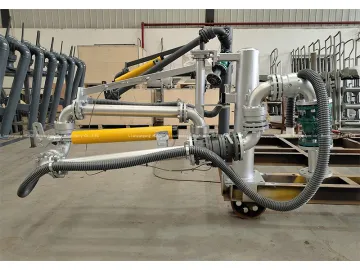 PTFE Lined Loading Arm
-
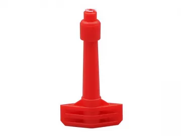 Screw On Spout, LW089
-
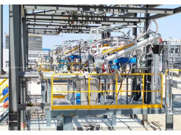 Top Loading Skid
-
 Screw On Spout, LW098
-
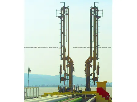 Marine Loading Arm (Manual Operation)
-
 Screw On Spout, LW097
-
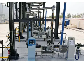 Bottom Loading Arm with API Coupler
-
 THVA-63 over and under voltage, over current protection relay, 40A 63A rated current

