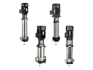
Vertical Multi-Stage Centrifugal Pump
BL(T) series stainless steel multi-stage centrifugal pump (afterwards called pump) boasts characters of high efficiency, low noise, steady operation, etc. The hydraulic pump set adopts the non-self-priming vertical multi-stage structure, ensuring a compact body, easy installation, convenient operation and maintenance.
Application Limits of Vertical Pump
Medium temperature: normal type: 0℃~68℃ hot water type: 0℃~120℃ Ambient temperature: 40℃
Max ambient pressure: 1.0MPa
Advisable to use motor of higher power in case that the density or viscosity of medium is above that of water.
pH: 5 to 8
Application Fields of Centrifugal Pump
| Water supply | BL | BL T |
| Filtration and transfer at waterworks | ● | ● |
| Distribution from waterworks | ● | ● |
| Pressureboosting in mains | ● | ● |
| Pressure boosting in high-rise buildin g s, hotels, etc. | ● | ● |
| Pressure boosting for industrial water supply | ● | ● |
| Industry | ||
| Pressure boosting | ● | ● |
| Process water systems | ● | ● |
| Washing and cleaning systems | ● | ● |
| Vehicle washing tunnels | ● | ● |
| Fire fighting systems | ● | ● |
| Liquid transfer | ||
| Cooling and air-conditioning systems(refrigerants) | ● | ● |
| Boiler feed and condensate systems | ● | ● |
| Machine tools(cooling lubricants) | ● | ● |
| Aquafarming | ● | ● |
| Transfer | ● | ● |
| Oil and alcohol | ● | ● |
| Glycol and coolants | ● | ● |
| Water treatment | ||
| Ultra-filtration systems | ● | ○ |
| Reverse osmosis systems | ● | ○ |
| Softening, ionising, demineralizing systems | ● | ○ |
| Distillation sys tems | ● | ○ |
| Separators | ● | ○ |
| Swimming baths | ● | ● |
| lrrigation | ||
| Field irrigation(flooding) | ● | ● |
| Sprinkler irrigation | ● | ● |
| Drip-feed irrigation | ● | ● |
Certificate
Electric Motor
Full-enclosed and ventilating two-pole standard motor
Protection class: IP55
Insulation class: F
Standard voltage Single phase 220V-50Hz Three phase: 380/400V-50Hz
Standard motor efficiency: 11kW to 45kW:IE3, other: IE2, specific efficiency value for below table
Energy Efficiency Standard (IEC60034)
Calculation of minimum Inlet Pressure
If the pressure in pump is lower than the vapor pressure of medium, cavitation will occur, which will affect the performance of pump. To avoid the cavitation and ensure the pump inlet has a minimum pressure, maximum suction head should be calculated as below:
H=Pbx10.2-NPSH-Hf-hv-Hs
Pb: Atmospheric pressure, bar (In close pipeline system, it can be considered as the system pressure);
NPSH: Net positive suction head, m (Value at maximum flow of Q-NPSH curve);
Hf: Suction pipe line loss (Value at maximum flow of corresponding pipeline);
Hv: Medium vapor pressure, m (Medium vapor pressure at corresponding temperature, the default medium is water, as shown in figure4 on the right);
Hs: Safety margin, m, general value is 0.5.
Calculation result: if H is positive, the pump is installed in suction way, otherwise, it is installed in downdraft way.
Note: It is not necessary to do above calculation under general conditions. Only when we use pump in the following situations do we need to calculate the H:
1. Medium temperature is high;
2. The velocity of flow is larger than rated value;
3. Suction head is big or inlet pipeline is long;
4. System pressure is small;
5. Inlet condition is bad.
Selection of Pumps
Selection of pumps should be based on:
1. Duty point of the pump
2. Dimensional data such as pressure loss as a result of height differences, friction loss in the pipework
3. Pump efficiency
4. Pump materials
5. Pump connections
6. Commonly used mechanical seal configuration tables
1. Duty point of the Pump
From a duty point it is possible to select a pump on the basis of the curve charts shown in "performance curves/technical" data.
2. Dimensional Data
When sizing a pump the following must be taken into account:
· Required flow and pressure at the draw-off point.
· Pressure loss as a result of height differences.
· Friction loss in the pipework (Hf) (Refer to Fig.1) it may.
· Highest efficiency at the estimated duty point.
· NPSH value.
· For calculation of the NPSH value, see corresponding curves chart.
3. Pump Efficiency
Before determining the best efficiency point, the operation pattern of the pump needs to be identified. If the pump expected to operate as the same duty point, then select a BL pump which is operating at a duty point corresponding with the best efficiency of the pump.
As the pump is sized on the basis of the highest possible flow, it is important always to have the duty point to the right on the efficiency curve (eta) in order to keep efficiency high when the flow drops.
4. Pump Material
The material variant should be selected based of the liquid to be pumped. BL wetted parts are made of AISI304. BLT pump body is made of cast-iron.
5. Pump Connections
Selection of pump connection depends on the rated pressure and pipe work. The vertical centrifugal pump offers a wide range of flexible connections such as:
· Pipe thread
· Oval flange
· DIN flange
· Other connections on request
· Commonly used mechanical seal configuration tables
6. Commonly used mechanical seal configuration tables
| Configuration | Configuration illustrate | Application Field | Configuration case |
| EUBV | Container-type E, hard alloy moving ring U, static ring leaching resin graphite B, fluorine rubber V | 1. Working condition regular under cold water 0 ℃ to 68 ℃ , no particles, oil.2. Working condition regular under hot water 68 ℃ to 90 ℃ , no particles, with oil. | Normal |
| EQQE | Container type E, moving ring and static ring silicon carbide Q, epdm E | Working condition: hot water 90 ℃ to 120 ℃ , containing a small amount of particles, no oil. | Normal |
| EQQV | Container type E, moving ring and static ring silicon carbide Q, fluorine rubber V | 1. PH = 5-7 acidic medium.2. PH = 7-9, alkaline medium.3. Working conditions: hot water 68 ℃ to 90 ℃ , containing a small amount of particles, oil.4. With oil. | Customer-made |
| EUUE | Container type E, moving ring and statil ring U, hard alloy U, epdm E | 1. Under ice water 0 ℃ .2. A crystallization of alkaline medium.3. Containing a large number of granular media.4. More than 2 MPa pressure condition. 5. No oil. | Customer-made |
Maximum Work Pressure
| Model | Curve No. |
| BL(T)2,4 | 2 |
| BL(T)8,12,16,20 | 3 |
| BL(T)32-2-2~BL(T)32-7 | 1 |
| BL(T)32-8-2~BL(T)32-12 | 4 |
| BL(T)32-13~BL(T)32-15-2 | 5 |
| BL(T)45-2-2~BL(T)45-6 | 1 |
| BL(T)45-7-2~BL(T)45-9 | 4 |
| BL(T)45-10-2~BL(T)45-13-2 | 5 |
| BL(T)64-2-2~BL(T)64-5-2 | 1 |
| BL(T)64-5-1~BL(T)64-8 | 4 |
| BL(T)90-2-2~BL(T)90-4-2 | 1 |
| BL(T)90-4~BL(T)90-6 | 4 |
The limits of pressure and temperature are shown in the following fig. 4, the pressure and temperature are shown in the fig. 4.
Maximum Ambient Temperature
When the pump is operating in the place where ambient temperature is higher than 40℃ or altitude is higher than 1000m, the output power of motor P2 will decrease because of poor cooling caused by low air density. Therefore, in that case, the vertical pump should be equipped with high-power motor.
Performance Range
Product Range
Links:https://www.globefindpro.com/products/40192.html
-
 TCT Construction Saw Blade
-
 TCT Saw Blade for Bamboo Cutting
-
 TCT Multi-Rip Saw Blade with Rakers
-
 TCT Saw Blade for Wood Trimming
-
 Pneumatic Comparator HS721
-
 Pneumatic Comparator HS701
-
 Q(D)Y-K2 Multi-stage Submersible Pump
-
 PW-Z Self-Priming Peripheral Pump
-
 QT Peripheral Pump
-
 Electronic Pressure Comparator HS315&HS316&HS318
-
 WQ-QG Grinder Pump
-
 Electronic Pressure Comparator HS316L&HS317L