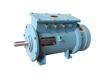
Three-Phase Marine Induction Motor (for Side Thruster)
Introduction
Introduction
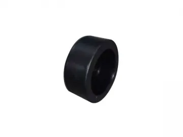
The YCTJ-H series of three phase marine induction motor for side thrusters is a completely enclosed, fan-cooled induction motor which works for power supply systems in all kinds of ships. The motor is the side thruster radiator and has a low starting current and high starting torque.
Construction
1. IP44 or IP23 protection rating
2. Material: HT200 cast iron frame with cooling ribs
3. Cylindrical shaft extension
4. Terminal box conforms to IEC IEC60034-8.The electric clearance is no less than 8mm and the creepage distance is no less than 12mm. Another binding post in the terminal box functions as a grounding connection.
Operating Conditions
Operating Conditions
Temperature of ambient air: 0℃~45℃
Altitude: 0M
Relative humidity: ≤95%
Dew: exists
Oil mist: exists
Fungus: exists
Shock: exists
Vibration: exists
Inclination and swing: ±22.5°
Rated voltage and frequency: 50HZ.380V or 60HZ.440V
Connection: Δ(Y)
Duty type: continuous (S1)or S2-30 type
Insulation: B or F
Temperature rise of winding: 75K or 100K
Permissible working temperature of bearing: 90℃
(Thermometer method)
Type of starting: Direct on full-voltage starting for all sizes; reduced voltage starting allowable at no-load.
Vibration and Noise
The effective values of vibration velocity, measured at the no-load conditions, do not exceed those given in table 2.
| Frame Size | The effective values of vibration velocity mm/s |
| 160~225 | 2.8 |
| 250~355 | 3.5 |
| 400 and above | 4.5 |
The following table 3 shows the noise condition when the motor is in no-load. Table 3
| Power kW | Synchronous speed r/min | |||||||
| 3600 | 3000 | 1500, 1800 | 1000, 1200 | 750, 900 | 600 、 720 | |||
| Sound power level dB ( A ) | ||||||||
| 4 | - | - | - | - | 69 | - | ||
| 5.5 | 69 | |||||||
| 7.5 | 75 | 72 | ||||||
| 11 | 87 | 87 | 82 | 75 | 72 | |||
| 15 | 87 | 87 | 82 | 78 | 75 | |||
| 18.5 | 87 | 87 | 82 | 78 | 75 | |||
| 22 | 92 | 92 | 82 | 78 | 78 | |||
| 30 | 95 | 95 | 84 | 81 | 78 | |||
| 37 | 95 | 95 | 84 | 81 | 78 | |||
| 45 | 97 | 97 | 84 | 84 | 78 | 87 | ||
| 55 | 97 | 97 | 86 | 84 | 81 | 87 | ||
| 75 | 99 | 99 | 92 | 90 | 87 | 87 | ||
| 90 | 99 | 99 | 92 | 90 | 87 | 92 | ||
| 110 | 104 | 104 | 98 | 92 | 87 | 92 | ||
| 132 | 105 | 104 | 101 | 92 | 99 | 92 | ||
| 160 | 105 | 104 | 101 | 102 | 99 | 97 | ||
| 200 | 105 | 104 | 101 | 102 | 99 | 97 | ||
| 250 | 113 | 111 | 108 | 105 | 101 | 99 | ||
| 315 | 113 | 111 | 108 | 108 | 105 | 101 | ||
| 355 | 115 | 113 | 111 | 111 | 105 | 101 | ||
| 400 | 115 | 113 | 111 | 111 | 108 | - | ||
| 450 | 116 | 113 | 111 | 111 | - | |||
| 500 | 118 | 116 | 115 | - | ||||
| 560 | 118 | 116 | 115 | |||||
Main Technical Data Technical Data
The protection grade of frame sizes and power supply: Table 4 shows IP23 data, and Table 5 shows IP44 data. Table 4
| Frame Size | Number of Poles | ||||
| 2 | 4 | 6 | 8 | 10 | |
| Power kW | |||||
| 160M | 15 | 11 | 7.5 | 5.5 | - |
| 160L 1 | 18.5 | 15 | 11 | 7.5 | |
| 160L 2 | 22 | 18.5 | - | - | |
| 180M | 30 | 22 | 15 | 11 | |
| 180L | 37 | 30 | 18.5 | 15 | |
| 200M | 45 | 37 | 22 | 18.5 | |
| 200L | 55 | 45 | 30 | 22 | |
| 225S | 75 | 55 | 37 | 30 | |
| 225M | 90 | 75 | 45 | 37 | |
| 250M | 110 | 90 | 55 | 45 | |
| 280S | - | 110 | 75 | 55 | |
| 280M | 132 | 132 | 90 | 75 | |
| 315S | 160 | 160 | 110 | 90 | 55 |
| 315M | 200 | 200 | 132 | 110 | 75 |
| 315L | 250 | 250 | 160 | 132 | 90 |
| 355M | 315 | 315 | 200 | 160 | 110 |
| 355L | 355 | 355 | 250 | 200 | 132 |
| 400M 1 | 400 | 400 | 315 | 250 | 160 |
| 400M2 | 450 | 450 | 355 | 200 | |
| 400L 1 | 500 | 500 | 400 | 315 | 250 |
| 400L 2 | 560 | 560 | 450 | 355 | 315 |
| Frame Size | Number of Poles | ||||
| 2 | 4 | 6 | 8 | 10 | |
| Power kW | |||||
| 160M 1 | 11 | 11 | 7.5 | 4 | - |
| 160M2 | 15 | 5.5 | |||
| 160L | 18.5 | 15 | 11 | 7.5 | |
| 180M | 22 | 18.5 | - | - | |
| 180L | - | 22 | 15 | 11 | |
| 200L 1 | 30 | 30 | 18.5 | 15 | |
| 200L 2 | 37 | 22 | |||
| 225S | - | 37 | - | 18.5 | |
| 225M | 45 | 45 | 30 | 22 | |
| 250M | 55 | 55 | 37 | 30 | |
| 280S | 75 | 75 | 45 | 37 | |
| 280M | 90 | 90 | 55 | 45 | |
| 315S | 110 | 110 | 75 | 55 | 45 |
| 315M | 132 | 132 | 90 | 75 | 55 |
| 315L 1 | 160 | 160 | 110 | 90 | 75 |
| 315L 2 | 200 | 200 | 132 | 110 | 90 |
| 355M 1 | 250 | 250 | 160 | 132 | 110 |
| 355M2 | 200 | 160 | 132 | ||
| 355L | 315 | 315 | 250 | 200 | 160 |
| 400M 1 | 355 | 355 | 280 | 220 | 200 |
| 400M2 | 400 | 400 | 315 | 250 | |
| 400M3 | 450 | 450 | - | - | |
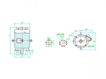
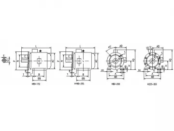
Mounting and Overall Dimensions
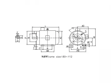
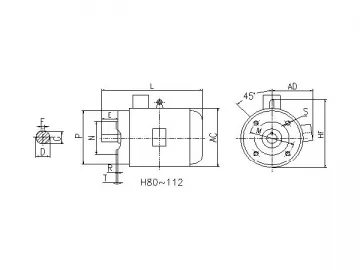
Mounting and overall dimensions for motors with various mounting arrangements are shown below in photos 1 and 2 and tables 6 and 7.
| Frame Size | Flange Size | Mounting Dimensions and Tolerance | Overall Dimensions | ||||||||||||||
| D | E | F | G | M | N | P | R | S | T | Number of flange holes | AC | AD | HF | L | |||
| 160M | FF300 | 42 | 110 | 12 | 37 | 300 | 250 | 350 | 0 | 19 | ф1.5 M | 5.0 | 4 | 325 | 270 | 450 | 660 |
| 160L | 705 | ||||||||||||||||
| 180M | 48 | 14 | 42.5 | 360 | 290 | 490 | 730 | ||||||||||
| 180L | 765 | ||||||||||||||||
| 200L | FF350 | 55 | 16 | 49 | 350 | 300 | 400 | 400 | 355 | 550 | 840 | ||||||
| 225S | FF400 | 55/60 | 110/140 | 18 | 49/53 | 400 | 350 | 450 | 8 | 450 | 370 | 610 | 890 | ||||
| 225M | 865/915 | ||||||||||||||||
| 250M | FF500 | 60/65 | 140 | 53/58 | 500 | 450 | 550 | 495 | 455 | 640 | 995 | ||||||
| 280S | 65/75 | 18/20 | 58/67.5 | 550 | 470 | 720 | 1090 | ||||||||||
| 280M | 1140 | ||||||||||||||||
| 315S | FF600 | 65/80 | 170 | 18/22 | 58/71 | 600 | 550 | 660 | 24 | ф2.0 M | 6.0 | 645 | 576 | 900 | 1390 | ||
| 315M | 1490 | ||||||||||||||||
| 315L | 1490 | ||||||||||||||||
| 355M | FF740 | 75/95 | 22/25 | 67.5/86 | 740 | 680 | 800 | 750 | 680 | 1035 | 1675 | ||||||
| 355L | 1675 | ||||||||||||||||
| 400M | FF940 | 90/110 | 210 | 22/28 | 81/100 | 940 | 880 | 1000 | 28 | 980 | 820 | 1010 | 1720 | ||||
| Note: a) R is the distance from the fitting surface of the flange to the shaft shoulder. b) The numerators of fractions in the table give the data of 2-pole motors while the denominators give data for motors with more than 4 poles. | |||||||||||||||||
Table 7 Motors featuring an end shield existing flange and a frame without a foot (IP44) unit: mm
| Frame size | Flange Size | Mounting Dimensions and Tolerance | Overall Dimensions | ||||||||||||||
| D | E | F | G | M | N | P | R | S | T | Number of flange holes | AC | AD | HF | L | |||
| 160M | FF300 | 42 | 110 | 12 | 37 | 300 | 250 | 350 | 0 | 19 | ф1.5 M | 5.0 | 4 | 325 | 270 | 450 | 660 |
| 160L | 705 | ||||||||||||||||
| 180M | 48 | 14 | 42.5 | 360 | 290 | 490 | 730 | ||||||||||
| 180L | 765 | ||||||||||||||||
| 200L | FF350 | 55 | 16 | 49 | 350 | 300 | 400 | 400 | 355 | 550 | 840 | ||||||
| 225S | FF400 | 55/60 | 110/140 | 18 | 49/53 | 400 | 350 | 450 | 8 | 450 | 370 | 610 | 890 | ||||
| 225M | 865/915 | ||||||||||||||||
| 250M | FF500 | 60/65 | 140 | 53/58 | 500 | 450 | 550 | 495 | 455 | 640 | 995 | ||||||
| 280S | 65/75 | 18/20 | 58/67.5 | 550 | 470 | 720 | 1090 | ||||||||||
| 280M | 1140 | ||||||||||||||||
| 315S | FF600 | 65/80 | 170 | 18/22 | 58/71 | 600 | 550 | 660 | 24 | ф2.0 M | 6.0 | 645 | 576 | 900 | 1390 | ||
| 315M | 1490 | ||||||||||||||||
| 315L | 1490 | ||||||||||||||||
| 355M | FF740 | 75/95 | 22/25 | 67.5/86 | 740 | 680 | 800 | 750 | 680 | 1035 | 1675 | ||||||
| 355L | 1675 | ||||||||||||||||
| 400M | FF940 | 90/110 | 210 | 22/28 | 81/100 | 940 | 880 | 1000 | 28 | 980 | 820 | 1010 | 1720 | ||||
| Note: a) R is the distance from the fitting surface of the flange to the shaft shoulder. b) The numerators of fractions in the table give the data of 2-pole motors while the denominators give the data of motors with more than 4 poles. | |||||||||||||||||
Links:https://www.globefindpro.com/products/41086.html
-
 RPAP5 Composite Pipes and Fittings
-
 Geothermal Piping System (for GSHP)
-
 Three-Phase Induction Motor, YX3 Series
-
 Aluminum Frame Wicker Sofa
-
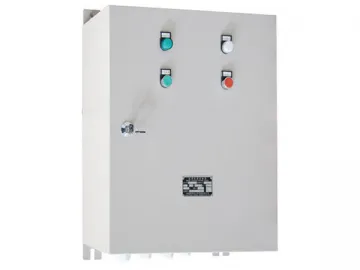 Marine Motor Control Panel
-
 Ultra-High Efficiency Three-phase Induction Motor
-
 Three-phase Induction Motor (for Lifting)
-
 PEX Composite Pipes and Fittings
-
 PEX Pipes and Fittings
-
 Municipal Drain Pipe System
-
 Three-Phase Induction Motor, YE2 Series
-
 Double Wall Corrugated Pipes