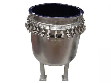
Glass-Lined Storage Tank, K Type
The K type glass lined storage tank features an open-type design. That means the cover and tank body are assembled using clamps and gasket, and they can be separated. This design ensures ease of maintenance and makes it convenient to replace parts. Due to special process, this type of glass lined receiver comes with relatively small volume. However, it offers exceptional corrosion resistance, sheer reliability, stable lining and long service life.
Standard K-Type Glass-Lined Storage Tank K-Type Glass-Lined Storage Tank with Lugs Mini Size K-Type Glass-Lined Storage Tank Products being Transported in Container
Various Specifications Available
According to different capacities, our open type glass lined storage tank is divided into various models including K50L, K100L, K200L, K300L, K500L, K1000L, K1500L, K2000L, etc. In addition to standard glass lined steel stank, we are also able to make non-standard products to customers' needs.
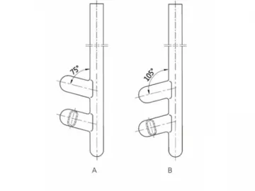
Technical Parameters of the Glass Lined Storage TankDesign Drawing
| Inner Vessel | |
| Design Pressure( MPa ) | ATM |
| Design Temperature( ℃ ) | -19 ℃ /150℃ |
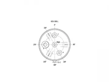
| Symbol | Usage |
| a | Handhole / Manhole |
| b | Medium Inlet |
| c, d, e | Spare |
| f1, f2 | Level Gauge Hole |
| g | Medium Outlet |
K50-K500L Nozzles Layout (Plan View)
K1000-K2000L Nozzles Layout (Plan View)
| Unite:mm | |||||||||
| Specifications | K50L | K100L | K200L | K300L | K500L | K1000L | K1500L | K2000L | |
| Nominal Capacity (L) | 50 | 100 | 200 | 300 | 500 | 1000 | 1500 | 2000 | |
| Total Capacity (L) | 80 | 155 | 294 | 447 | 740 | 1480 | 2020 | 2800 | |
| Calculated Capacity(Notes 1) (L) | 61 | 121 | 237 | 362 | 620 | 1270 | 1670 | 2370 | |
| Reference Weight (kg) | 95 | 160 | 210 | 285 | 395 | 716 | 970 | 1266 | |
| MainDimension | d1 | 400 | 500 | 600 | 700 | 800 | 1000 | 1200 | 1300 |
| d2 | 320 | 350 | 420 | 420 | 480 | 600 | 720 | 780 | |
| d3 | 280 | 350 | 420 | 490 | 560 | 700 | 700 | 910 | |
| h1 | 520 | 660 | 890 | 1000 | 1310 | 1695 | 1580 | 1895 | |
| h2 | 249 | 274 | 309 | 334 | 390 | 439 | 490 | 514 | |
| h | 1150 | 1095 | 1340 | 1750 | 1885 | 2310 | 2240 | 2670 | |
| n-Φ | 3-Φ15 | 3-Φ20 | 3-Φ20 | 3-Φ25 | 3-Φ25 | 3-Φ25 | 3-Φ25 | 3-Φ25 | |
| Nozzle DN | a | 80 | 100 | 125 | 125 | 150 | 150 | 200 | 300×400 |
| b | 65 | 65 | 65 | 80 | 80 | 80 | 100 | 100 | |
| c | 65 | 65 | 65 | 65 | 80 | 80 | 80 | 80 | |
| d | / | / | / | / | / | 80 | 80 | 80 | |
| e | 65 | 65 | 65 | 65 | 65 | 80 | 80 | 80 | |
| f1 | / | 65 | 65 | 65 | 65 | 65 | 65 | 65 | |
| f2 | / | 65 | 65 | 65 | 65 | 65 | 65 | 65 | |
| g | 65 | 65 | 65 | 80 | 80 | 80 | 100 | 100 | |
| Notes 1: Calculated Capacity: Volume under highneck flange | |||||||||
Scan QR to Read
Links:https://www.globefindpro.com/products/41439.html
Links:https://www.globefindpro.com/products/41439.html
Recommended Products
-
 1-5L Agrochemicals Packaging Machine
-
 Glass-Lined Stainless Steel Equipment
-
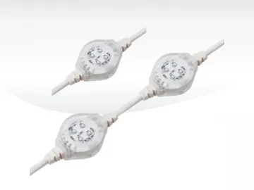 LED Light (for Dot Matrix), PX3A
-
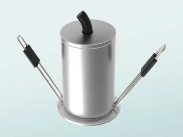 LED Downlight, OR3A
-
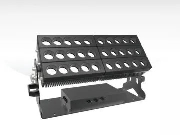 LED Wall Washer (Outdoor), TF6A
-
 LED Downlight, OR3C
-
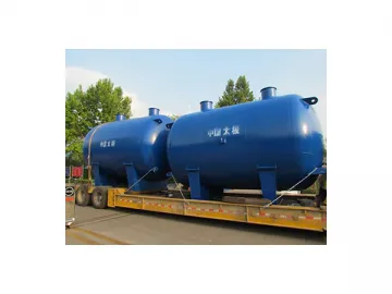 Glass-Lined Storage Tank, Horizontal Type
-
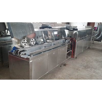
 Horizontal Form Fill Seal Machine, DXD-130
-
 Glass-Lined Thermowell
-
 Automatic Flap-Folding Carton Sealer,FX-02
-
 Single-Head Automatic Screw Capper,FX-1A
-
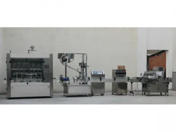
 Carton Packaging Line
Hot Products