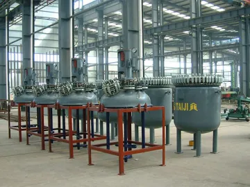
Glass-Lined Reactor, K Type
Main Features
1. The K type glass lined reactor is a reactor designed with separable cover and body. The cover is fastened to the body using clamps, with gaskets between them.
2. Generally, this pressure vessel is suitable for the small capacity chemical processing works.
3. Since the cover can be separated from the body, the chemical process equipment comes with a diversity of agitating methods and is excellent for all kinds of users.
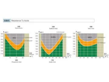
4. Made from TJ09 high end enamel, combining proven and sophisticated enameling technology, this open type glass lined reactor provides remarkable resistance to corrosion, impact and severe change of temperature as well as reliable durability.
5. According to capacities, Our K type glass lined reactors are available in K50L, K100L, K200L, K300L, K500L, K1000L, K1500L, K2000L, K3000L, K4000L, K5000L, K6300L, K8000L, K10000L, K12500L, K16000L and other models. They ensure ease of use and maintenance.
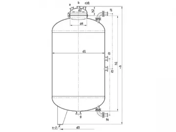
Design Drawing of K50L-K500L Glass-Lined Reactor
| Internal Vessel | Jacket | |
| Design Pressure( MPa ) | 0.4/0.6/1.0 | 0.6/1.0 |
| Design Temperature( ℃ ) | -19 ℃ /200 ℃ | -19 ℃ /200 ℃ |
| Symbol | Usage |
| a | Manhole |
| b | Agitator Hole |
| c | Thermowell |
| d | Medium Outlet |
| e1,e2 | Sightglass |
| f, g | Spare |
| k1, k2, k3 | In/Outlet |
| m | Vent Hole |
K50L-K100L Design Drawing (Plan View)
K50L-K100L Design Drawing (Plan View)
| Unit: mm | ||||||
| Specifications | K50L | K100L | K200L | K300L | K500L | |
| Nominal Capacity (L) | 50 | 100 | 200 | 300 | 500 | |
| Total Capacity (L) | 102 | 180 | 325 | 483 | 743 | |
| Calculated Capacity (Notes 1) (L) | 71 | 128 | 247 | 369 | 588 | |
| Jacket Capacity (L) | 21 | 32 | 57 | 92 | 130 | |
| Heat Exchange Area (m2 ) | 0.34 | 0.66 | 1.26 | 1.75 | 2.64 | |
| Reference Weight (kg) | 420 | 490 | 650 | 920 | 1140 | |
| MainDimension | d1 | 500 | 600 | 700 | 800 | 900 |
| d2 | 600 | 700 | 800 | 900 | 1000 | |
| d3(Notes 2) | 706 | 816 | 918 | 1028 | 1130 | |
| d4 | 420 | 520 | 620 | 720 | 810 | |
| d5 | 300 | 300 | 400 | 500 | 500 | |
| h1 | 400 | 500 | 700 | 800 | 1000 | |
| h2 | 274 | 309 | 354 | 390 | 415 | |
| h3 | 220 | 250 | 270 | 280 | 280 | |
| h4 | 300 | 340 | 370 | 390 | 400 | |
| h | 1785 | 1930 | 2195 | 2545 | 2985 | |
| B | 250 | 250 | 250 | 250 | 270 | |
| Φ | 14 | 18 | 18 | 23 | 23 | |
| Nozzle DN | a | 80 | 80 | 125 | 125 | 150 |
| b | 65 | 65 | 100 | 100 | 100 | |
| c | 65 | 65 | 65 | 65 | 65 | |
| d | 65 | 65 | 80 | 80 | 80 | |
| e1 | 65 | 65 | 65 | 65 | 80 | |
| e2 | / | / | 65 | 65 | 80 | |
| f | 65 | 65 | 80 | 80 | 100 | |
| g | / | / | 65 | 65 | 125 | |
| JacketNozzle DN | k1 | 20 | 20 | 25 | 25 | 32 |
| k2 | 20 | 20 | 25 | 25 | 32 | |
| k3 | 20 | 20 | 25 | 25 | 32 | |
| m | G3/8'' | G3/8'' | G3/8'' | G3/8'' | G3/8'' | |
| Drive | DN | 40 | 40 | 50 | 65 | 65 |
| h5 | 950 | 950 | 953 | 1170 | 1170 | |
| Notes 1: Calculated Capacity: Volume under highneck flange. | ||||||
| Notes 2: Support types could be determined by users; Without special request, lugs would be normally applied. | ||||||
Design Drawing of K1000L-K6300L Glass-Lined Reactor
| Internal Vessel | Jacket | |
| Design Pressure( MPa ) | 0.4/0.6/1.0 | 0.6/1.0 |
| Design Temperature( ℃ ) | -19 ℃ /200 ℃ | -19 ℃ /200 ℃ |
| Symbol | Usage |
| a | Manhole |
| b | Agitator Hole |
| c | Thermowell |
| d, f, g, h | Spare |
| e | Sightglass |
| j | Medium Outlet |
| k1,k2,k3 | In/Outlet |
| n1,n2,n3 | Spray Nozzle |
| m | Vent Hole |
K1000L-K6300L Design Drawing (Plan View)
| Unit: mm | ||||||||
| Specifications | K1000L | K1500L | K2000L | K3000L | K4000L | K5000L | K6300L | |
| Nominal Capacity (L) | 1000 | 1500 | 2000 | 3000 | 4000 | 5000 | 6300 | |
| Total Capacity (L) | 1616 | 2172 | 2640 | 4170 | 5140 | 6470 | 7580 | |
| Calculated Capacity (Notes 1) (L) | 1244 | 1714 | 2180 | 3370 | 4334 | 5443 | 6561 | |
| Jacket Capacity (L) | 206 | 300 | 387 | 461 | 774 | 873 | 1027 | |
| Heat Exchange Area ( ㎡ ) | 4.55 | 5.76 | 7.23 | 9.33 | 11.85 | 13.74 | 16.43 | |
| Reference Weight (kg) | 1820 | 2280 | 2535 | 3555 | 4055 | 4940 | 5560 | |
| MainDimension | d1 | 1200 | 1300 | 1300 | 1600 | 1600 | 1750 | 1750 |
| d2 | 1300 | 1450 | 1450 | 1750 | 1750 | 1900 | 1900 | |
| d3(Notes 2) | 1468 | 1622 | 1622 | 1964 | 1964 | 2152 | 2152 | |
| d4 | 1080 | 1180 | 1180 | 1440 | 1440 | 1580 | 1580 | |
| d5 | 700 | 700 | 700 | 800 | 800 | 850 | 850 | |
| h1 | 1200 | 1400 | 1830 | 1810 | 2290 | 2410 | 2875 | |
| h2 | 494 | 519 | 519 | 594 | 594 | 632 | 632 | |
| h3 | 290 | 330 | 330 | 340 | 340 | 340 | 340 | |
| h4 | 600 | 650 | 650 | 700 | 700 | 700 | 700 | |
| h | 3450 | 3700 | 4050 | 4210 | 4650 | 4820 | 5470 | |
| B1 | 315 | 315 | 315 | 315 | 315 | 350 | 350 | |
| B2 | / | 510 | 510 | 510 | 510 | 510 | 510 | |
| Φ | 30 | 30 | 30 | 30 | 30 | 30 | 30 | |
| Nozzle DN | a | 300×400 | 300×400 | 300×400 | 300×400 | 300×400 | 300×400 | 300×400 |
| b | 125 | 125 | 125 | 150 | 150 | 150 | 150 | |
| c | 100 | 100 | 100 | 100 | 100 | 125 | 125 | |
| d | 100 | 100 | 100 | 100 | 100 | 125 | 125 | |
| e | 100 | 125 | 125 | 125 | 125 | 125 | 125 | |
| f | 125 | 125 | 125 | 125 | 125 | 150 | 150 | |
| g | 100 | 100 | 100 | 100 | 100 | 125 | 125 | |
| h | 100 | 125 | 125 | 125 | 125 | 150 | 150 | |
| j | 100 | 100 | 100 | 125 | 125 | 125 | 125 | |
| JacketNozzle DN | k1 | 32 | 40 | 40 | 50 | 50 | 65 | 65 |
| k2 | 32 | 40 | 40 | 50 | 50 | 65 | 65 | |
| k3 | 32 | 40 | 40 | 50 | 50 | 65 | 65 | |
| n1 | / | 50 | 50 | 65 | 65 | 65 | 65 | |
| n2 | / | 50 | 50 | 65 | 65 | 65 | 65 | |
| n3 | / | / | / | / | 65 | 65 | 65 | |
| m | G3/8'' | G3/8'' | G3/8'' | G3/8'' | G3/8'' | G3/8'' | G3/8'' | |
| Drive | DN | 80 | 80 | 80 | 95 | 95 | 95 | 95 |
| h5 | 1320 | 1320 | 1320 | 1360 | 1360 | 1360 | 1530 | |
| Notes 1: Calculated Capacity: Volume under highneck flange. | ||||||||
| Notes 2: Support types could be determined by users; Without special request, lugs would be normally applied. | ||||||||
Design Drawing of K8000L-K16000L Glass-Lined Reactor
| Internal Vessel | Jacket | |
| Design Pressure( MPa ) | 0.2/1.0 | 0.6/1.0 |
| Design Temperature( ℃ ) | -19 ℃ /200 ℃ | -19 ℃ /200 ℃ |
| Symbol | Usage |
| a | Medium Outlet |
| b1,b2,b3,b4 | In/Outlet |
| c | Manhole |
| d | Agitator Hole |
| e1 | Thermowell |
| e2,g1,g2,g3,g4,k | Spare |
| h | Sightglass |
| m | Vent Hole |
| n | Clean Hole |
Design Drawing of K8000L-K16000L Glass-Lined Reactor
| Unit: mm | |||||
| Specifications | K8000L | K10000L | K12500L | K16000L | |
| Nominal Capacity (L) | 8000 | 10000 | 12500 | 16000 | |
| Total Capacity (L) | 10190 | 12750 | 15250 | 18493 | |
| Calculated Capacity(Notes 1) (L) | 8850 | 10900 | 13400 | 16680 | |
| Jacket Capacity (L) | 1724 | 1940 | 2324 | 2500 | |
| Heat Exchange Area ( ㎡ ) | 19.6 | 21.54 | 26.5 | 28 | |
| Reference Weight (kg) | 7810 | 8720 | 10155 | 11700 | |
| MainDimension | d1 | 2000 | 2200 | 2200 | 2400 |
| d2 | 2200 | 2400 | 2400 | 2600 | |
| d3(Notes 2) | 2452 | 2704 | 2704 | 2908 | |
| h1 | 3000 | 3060 | 3720 | 3740 | |
| h2 | 710 | 770 | 770 | 825 | |
| h3 | 380 | 400 | 400 | 460 | |
| h4 | 830 | 850 | 850 | 900 | |
| B1 | 400 | 470 | 470 | 470 | |
| B2 | 510 | 550 | 550 | 550 | |
| Φ | 30 | 36 | 36 | 36 | |
| Nozzle DN | a | 125 | 150 | 150 | 150 |
| c | 300×400 | 300×400 | 300×400 | 450 | |
| d | 200 | 200 | 200 | 200 | |
| e1 | 200 | 200 | 200 | 200 | |
| e2 | 150 | 200 | 200 | 200 | |
| g1 | 150 | 150 | 150 | 150 | |
| g2 | 150 | 150 | 150 | 150 | |
| g3 | 150 | 150 | 150 | 150 | |
| g4 | / | 150 | 150 | 150 | |
| h | 125 | 125 | 125 | 125 | |
| k | 125 | 125 | 125 | 125 | |
| JacketNozzle DN | b1 | 65 | 80 | 80 | 100 |
| b2 | 65 | 80 | 80 | 100 | |
| b3 | 65 | 80 | 80 | 100 | |
| b4 | / | 80 | 80 | 100 | |
| f1 | 65 | 80 | 80 | 100 | |
| f2 | 65 | 80 | 80 | 100 | |
| f3 | 65 | 80 | 80 | 100 | |
| m | G3/4'' | G3/4'' | G3/4'' | G3/4'' | |
| n | G1/2'' | G1/2'' | G1/2'' | G1/2'' | |
| Drive | DN | 110 | 110 | 110 | 130 |
| h5 | 1375 | 1375 | 1375 | 1995 | |
| Notes 1: Calculate Capacity: Volume under highneck flange. | |||||
| Notes 2: Support types could be determined by users; With no special request, lugs would be normally applied. | |||||
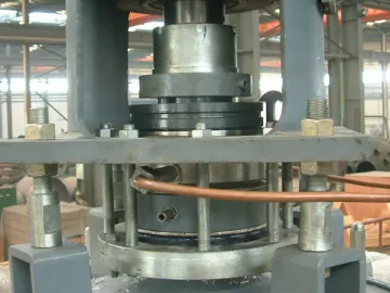
Front View Side View Bottom View Cross Section View Interior View Mini K-Type Glass-Lined Reactor Production Line of Standard Reactor
Links:https://www.globefindpro.com/products/41462.html
-
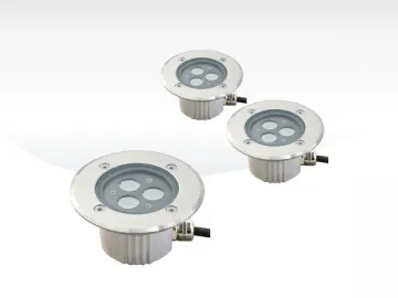 In-Ground / Underwater LED light, GR2D
-
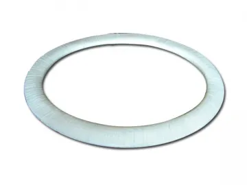 PTFE Envelope Gasket
-
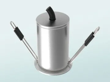
 Mechanical Seals
-
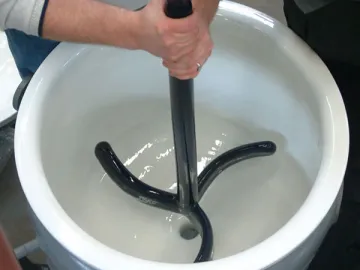 Glass-Lined Agitator
-
 Glass-Lined Storage Tank, F Type
-
 In-Ground / Underwater LED light, GRC1
-
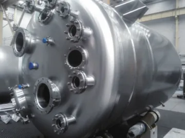 Stainless Steel Pressure Vessel
-
 Smart Light, B W
-
 LED Downlight, OR2C
-
 High Performance Enamel
-
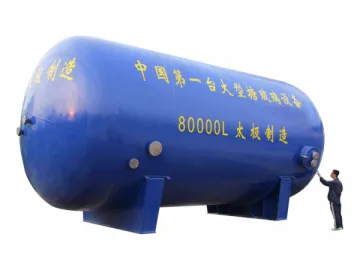 Glass-Lined Storage Tank
-
 LED Downlight, OR1A