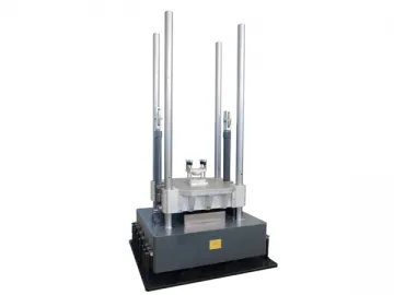
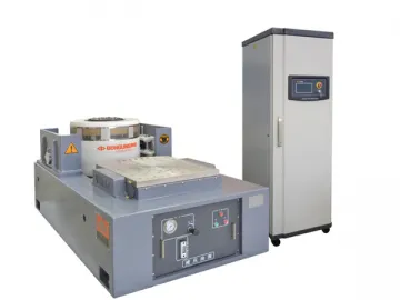
SY-10 Hydraulic Free Fall Shock Machine
The SY-10 hydraulic free fall shock machine is ideal for simulating the shock suffered by different goods in a practical environment. It checks whether these goods have reliable functions and complete structures under shock.
As a shock tester, the hydraulic free fall shock machine can carry out a variety of impact tests such as the conventional half-sine wave, post-peak sawtooth wave, and the square wave, etc.
Functions and Characteristics
1. A combination of hydraulic balance lifting system and multi-rack guide column with large strength margin ensures stable lifting action and no noise.
2. The cast aluminum-magnesium alloy table is optimally designed, featuring high stiffness and small high-frequency clutter.
3. With large braking force, the built-in hydraulic braking mechanism can effectively avoid the secondary rebound.
4. The digital lifting height feedback control system guarantees the repeatability of the shock.
5. The hydraulic free fall shock machine is designed with a self-buffer base for greatly reducing the shock to the ground. Without a dedicated base, it is extremely convenient to be installed.
Main Specifications
| Model | SY10-2 Mechanical | SY10-5 | SY10-25 | SY10-50 * | SY10-100 * | SY10-200 ** | SY10-400 ** | SY10-600 ** | SY10-1000 ** | SY10-1500 | ||||||||||||||||
| Related Load (kg) | 2 | 5 | 25 | 50 | 100 | 200 | 400 | 600 | 1000 | 1500 | ||||||||||||||||
| Table Size (mm) | 200x200 | 200x200 | 300x350 | 480x500 | 650x800 | 800x960 | 1000 X1000 | 1200 X1200 | 1000 X1000 1200 X1200 | 1000x1200 1200x1200 | ||||||||||||||||
| Shock Waveform | Half-sine | Half-sine | Post-peak sawtooth | Half-sine | Post-peak sawtooth | Half-sine | Post-peak sawtooth | Trapezoid | Half-sine | Post-peak sawtooth | Trapezoid | Half-sine | Post-peak sawtooth | Trapezoid | Half-sine | Post-peak sawtooth | Trapezoid | Half-sine | Post-peak sawtooth | Trapezoid | Half-sine | Post-peak sawtooth | Trapezoid | Half-sine | Post-peak sawtooth | Trapezoid |
| Shock Acceleration (m/s2) | 200-15000 | 200-15000 | 150-1000 | 150-15000 | 150-1000 | 150-6000 | 150-1000 | 300-1000 | 150-6000 | 150-1000 | 300-1000 | 150-3500 | 150-1000 | 300-1000 | 150-1500 | 150-500 | 300-500 | 150-1500 | 150-500 | 300-500 | 150-1500 | 150-500 | 300-500 | 150-1500 | 150-500 | 300-500 |
| Pulse Duration (ms) | 11-0.8 | 18-0.5 | 18-6 | 30-0.8 | 18-6 | 30-1.5 | 18-6 | 12-6 | 30-1.5 | 18-6 | 12-6 | 30-2 | 18-6 | 12-6 | 30-6 | 18-6 | 12-6 | 30-6 | 18-6 | 12-6 | 30-6 | 18-6 | 12-6 | 30-6 | 18-6 | 12-6 |
| Dimension (L×W×H: mm) | 900 x 510 x 2100 | 900x725x 2200 | 900x725x 2200 | 1260 x 960x 2600 | 1370 x 1000 x 2600 | 1560 x 1210 x 2600 | 1600 x 1210 x 2600 | 1620 x 1350 x 2600 | 1750x1500 x 2800 | 1950x1750x 2800 | ||||||||||||||||
| Weight (kg) | 500 | 550 | 850 | 2500 | 3100 | 3800 | 4200 | 5100 | 6000 | 7000 | ||||||||||||||||
| Size of Oil Source (mm) | 350×300×690 | 630×450×710 | 700X530X780 | |||||||||||||||||||||||
| Volume of Oil Source | 60L | 60L | 45kg/100L | |||||||||||||||||||||||
| Power Supply | 0.3kW | 380V 5060Hz 1.5kW | 380V 50/60Hz 1.5kW | 380V 50/60Hz 2.2kW | ||||||||||||||||||||||
| Standard | GJB150 GJB360 GJB548 GB/T2423 JJG541 IEC60068-2-27 | |||||||||||||||||||||||||
| *Minimum Pulse Width | 0.8ms | |||||||||||||||||||||||||
| **Minimum Pulse Width | 2ms | |||||||||||||||||||||||||
Links:https://www.globefindpro.com/products/44469.html
-
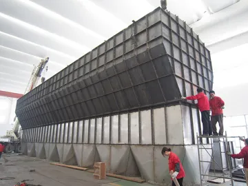
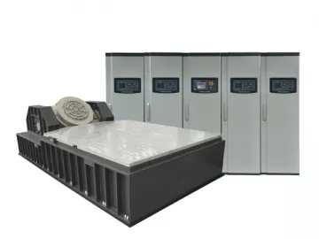 Water-cooled Vibration Test System
-
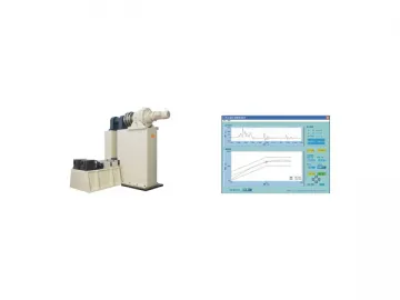 SY-14 Shock Response Spectrum Machine (SRS)
-
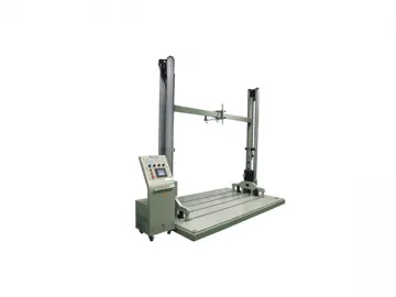
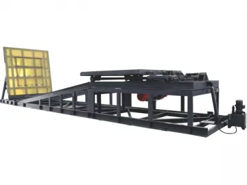 SY-15 Incline Impact Tester
-
 FG Fluid Bed Dryer
-
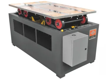 SY-50 Transport Simulation Tester
-
 Air-cooled Vibration Test System
-
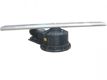
 SY-30 Centrifugal Constant Acceleration Tester
-
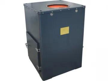
 SY-41 Pneumatic Drop Tester
-
 XF Horizontal Fluid Bed Dryer
-
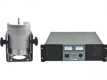 ESD Series Modal Exciter
-
 SY-31 Centrifugal Constant Acceleration Tester
-
 Vibstar Vibration Controller