Hydraulic Cutter B
Hydraulic Cutter B
for aerospace,the hydraulic cutter B is especially designed to dismantle the metalconstruction with round bar, section bar, cable, pipeline and deformed steelbar and plate to make the sufferers saved. With the advantages of light weight,strong cutting power and short time consumption of shears opening and closing,the equipment performs perfectly in accelerating the rescue process.
It must be connected to hydraulic power unitwhen working.
Structure ofthe Hydraulic Cutter
(1) Handle
(2) Hydraulic Cylinder
(3) Hydraulic Cylinder Cover
(4) Reversing Valve Handhold
(5) High Pressure Hose
(6) Blade Arm
Main Technical Parameters of the Hydraulic Cutter
| Max. Opening Distance of Blades | ≥ 150mm |
| Rated Working Pressure | 63MPa ( 630.000bar ) |
| Max. Cutting Capacity ( Q235 steel ) | 15mm ( Steel Plate );Φ 28mm ( Circle Steel ) |
| Max. Cutting Force | 390KN ( 39T ) |
| Opening Time without Load(Powered by motor pump) | ≤ 25s |
| Closing Time without Load(Powered by motor pump) | ≤ 30s |
| Weight(working condition) | ≤ 13.2kg |
| Dimension:L*W*H | 710*210*165mm |
Operation Principle
By connecting the motor or hand hydraulic pump through quick connector,the hydraulic fluid is supplied to the hydraulic cutter. Through theconnecting rod, the hydraulic pressure acting on the piston is transformedto the rotation of the shears. Then, the cutting material can be sheared toachieve the rescue service. The opening and closing of the shear is controlledby the manual reversing valve. When the manual reversing valve is at thecentral position, the shear cannot move, and the equipment is at the stateof oil return.
Features
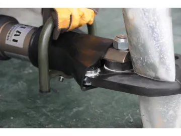
1. With the protective cover available for the movable part, theshear is made by the regrinding tool steel.
2. are available for safeguarding the operator.
3. cutting material in theblade center with the biggest cutting power easily.
Application Case of Cutting Metal Material
Links:https://www.globefindpro.com/products/46757.html
-
 13X-HP-E Molecular Sieve
-
 Hand Operated Combination Spreader Cutter
-
 Hydraulic Diamond Chain Saw
-
 Special molecular sieve
-
 GYDSD-17 Handheld Rebar Cutter
-
 Hydraulic Breaker
-
 Hydraulic Cutter A
-
 Lifting Air Cushion
-
 13X-APG Molecular Sieve
-
 Concrete Reinforcing Steel Corrosion Inhibitor
-
 Melamine Sulphonate Formaldehyde Condensate Concrete Admixture
-
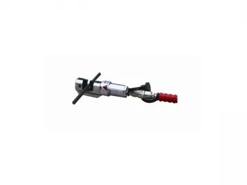 Hydraulic Rebar Cutter
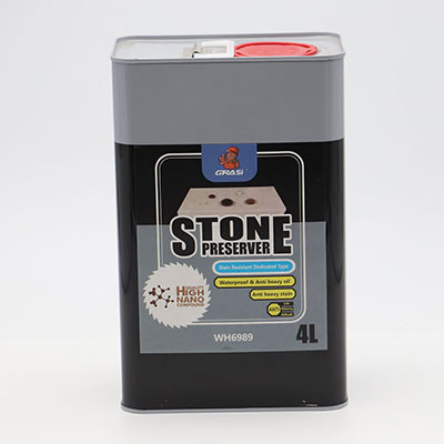 WH6989 Stone Curing Agent for Marble Granite Sandstone Limstone (Stain Resistant Special Effect Type)
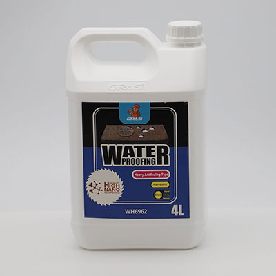 WH6962 Waterproof Penetrant Coating Agent for Mortar Cement Concrete (Super Anti-contamination Type)
