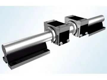
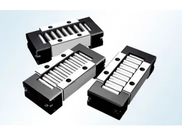
Cross Roller Guide
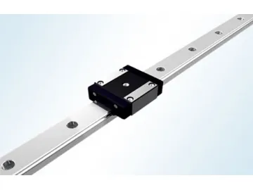
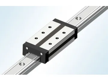
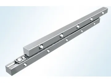
Our cross roller guide mainly consists of two rails with V type groove, retainer and cylindrical rollers. The rollers are arranged crosswise and shuttle along the precisely ground V type groove. Owing to the special design, the rollers could carry load from all directions.
The cross roller guide provides stable yet supple linear motion with lower rolling friction and starting friction. It has a unique roller retainer to achieve a large contact length of the rollers. The large contact area, coupled with small elastic deformation and many effective motion units, enables the cross roller guide to achieve easy motion under high load. Due to this reasonable design, the roller guide is easy to install and use.
The cross roller guide is widely used in applications requiring high precision. A smaller cross roller guide is suitable for linear motion parts of mold and instrument. A larger cross roller guide block could be used for plane linear motion of heavy machine tools and precision instrument, especially NC, CNC machine tools.
Rated Life of the Roller Cross Guide
Calculation of Rated Life
In formula: L---rated life ft---temperature coefficient fw---load coefficient C---rated dynamic load Pc---calculated load Temperature coefficient ft: If working temperature ≤100ºC, ft=1
Load coefficient fw
| Working condition | No outer impact or shock Speed is less than 15m/min | No obvious impact or shock Speed is less than 1.5~60m/min |
| fw | 1~1.5 | 1.5~2.0 |
Calculation of life time
In this formula: Lh---life time L---rated life l---travel length n---reciprocating times per minute
Load of Roller Cross Guide
Travel length and quantity of roller
Calculation of guide length
The length of guide is more than 1.5 times of travel: L>=1.5l
In formula: L---guide length(mm) l---travel length(mm)
The length of retainer: KsL---l/2
In formula: K---retainer length(mm)
Calculation of the roller quantity: N=(K-2a)/f+1
In formula: N---roller quantity (decimal fraction is not calculated) a---end distance of retainer f---roller interval
Calculation of Load
Tab-2
| Vertical Load | Side Load | |
| Load Direction | ||
| Rated Dynamic Load C | ||
| Rated Static Load C0 |
NOTE
C---rated dynamic load(N) C0---rated static load(N) C1---rated dynamic load of each roller(N) C01---rated static load of each roller(N) N---quantity of roller N/2---quantity of roller (decimal fraction is not calculated)
Accuracy Grade of Cross Roller Guide
| Item(mm) Accuracy grade(μm) grade | 2 | 3 | 4 | 5 | |
| Parallelism of rail's V-shape surface to A-side and B-side | ≤200 | 2 | 4 | 6 | 10 |
| >200-400 | 4 | 6 | 8 | 12 | |
| >400-600 | 5 | 8 | 12 | 14 | |
| >600-800 | 6 | 9 | 13 | 16 | |
| >800-1000 | 7 | 10 | 15 | 17 | |
| Limited deflection of height E | ±10 | ±10 | ±15 | ±20 | |
| Consistency of height E of rail in the same group | 10 | 10 | 15 | 20 | |
Code Rule and Dimensions of Cross Roller Guide
A set of cross roller guide consists of two rails. The quantity of the rails depends on the quantity of roller cross guide to be used on the same surface. As shown in above code rule II, there are two sets of roller cross guide on the same surface, namely, four rails are needed.
Basic Dimensions of Cross Roller Guide
Tab-4 unit: mm
| Specification Dimension | A | H | W | M | D | h | G | F | T | Max. Rail Length Lmax | Weight of One Rail per Meter(kg) |
| *GZV1 | 8.5 | 4 | 3.8 | M2 | - | - | 1.8 | 10 | 2 | 80 | 0.10 |
| *GZV2 | 12 | 6 | 5.5 | M3 | - | - | 2.5 | 15 | 2 | 180 | 0.23 |
| GZV3 | 18 | 8 | 8.4 | M4 | 6 | 3.1 | 3.5 | 25 | 3 | 300 | 0.45 |
| GZV4 | 22 | 11 | 10 | M5 | 7.5 | 4.1 | 4.5 | 40 | 3 | 500 | 0.75 |
| GZV6 | 31 | 15 | 14.2 | M6 | 9.5 | 5.2 | 6 | 50 | 3 | 800 | 1.47 |
| GZV9 | 44 | 22 | 20.2 | M8 | 10.5 | 6.2 | 9 | 50 | 4 | 1400 | 3.07 |
| GZV12 | 58 | 18 | 27 | M10 | 13.5 | 8.2 | 12 | 100 | 5 | 1400 | 5.32 |
| GZV15 | 71 | 36 | 33 | M12 | 16.5 | 10.2 | 14 | 100 | 5 | 1400 | 8.30 |
NOTE
*mark means the product is in development.
Basic Dimension of Retainer
| Specification Dimension | DM (mm) | a (mm) | f (mm) | B (mm) | C1 (KN) | C01 (KN) |
| *GZV1 | 1.5 | 1.5 | 2.5 | 3.8 | 0.107 | 0.118 |
| *GZV2 | 2 | 2 | 4 | 5.6 | 0.263 | 0.274 |
| GZV3 | 3 | 2.5 | 5 | 7.6 | 0.545 | 0.597 |
| GZV4 | 4 | 5 | 7 | 10 | 1.05 | 1.16 |
| GZV6 | 6 | 6 | 9 | 14 | 2.06 | 2.41 |
| GZV9 | 9 | 9.5 | 14 | 21 | 5.904 | 6.74 |
| GZV12 | 12 | 10 | 20 | 25 | 12.15 | 13.77 |
| GZV15 | 15 | 14 | 22 | 34 | 19.62 | 22.32 |
NOTE
C1: The rated dynamic load of each roller (KN)
C01: The rated static load of each roller (KN)
*mark means the product is in development.
Operation of Cross Roller Guide
Accuracy of equipped mounting surface
The structure of the equipped mounting surface of roller cross guide is shown separately as Fig-5
The accuracy of equipped mounting surface will have an influence on the running accuracy and performance. If the higher running accuracy is needed, the accuracy of the equipped mounting surface will be enhanced relatively.
A Surface: The accuracy will have an impact on the running accuracy directly
B&C Surface: plane: impact on preload
Verticality: The verticality against A surface has impact on assembly rigidity on the direction of preload. We suggest you try to improve the assembled surface accuracy. The accuracy value is close to the parallelism value.
Preload Method
The preload is adjusted by preload adjustable bolt. The dimension and specification of the bolt is the same as the fix bolt. The bolt center is half of rail height.
The value of preload depends on different machines and equipment. Over preload will reduce the life of the guide and damage the raceway. While in use, the cylindrical roller is easy to deflect, so it is self-locked, therefore no preload or lower preload is recommended. If there is higher accuracy and rigidity requirement, it is recommended to use fixed plane as shown diagram 7 or wedge block as shown diagram 8 to preload.
The roller cross guide is able to work under high temperature, but less than 100ºC. The speed of roller cross guide is less than 30m/min.
Lubrication of the Cross Roller Guide
Lubrication is used to reduce friction and avoid overheating. This protects the inner structure and ensures the function of the cross roller guide. If the roller cross guide moves at a high speed (V>=15m/min), N32 lubrication oil is recommended (refer to GB443-89), whose viscosity is 28.5~35.2 mm2/s when temperature is 40ºC. The cross roller guide should be lubricated periodically or connected with an oil hose for forced lubrication. Lithium grease (GB7324-94 2#) is recommended, if cross roller guide is running at low speed (V
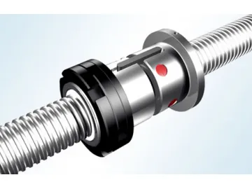
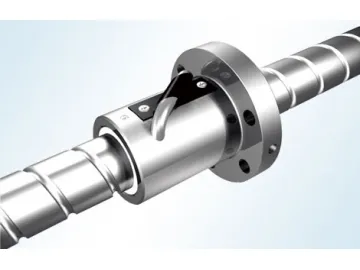
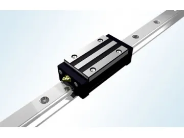
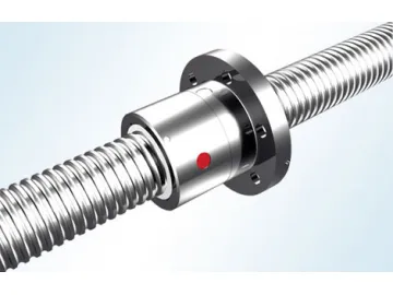
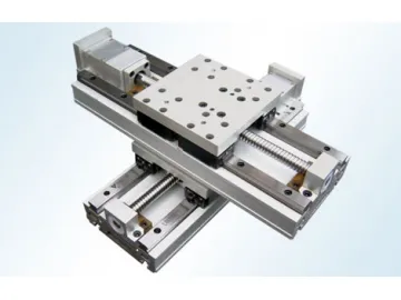
As an experienced cross roller guide manufacturer and supplier based in China, our company also offers radial linear guideway, convex linear motion spline, one axis CNC worktable, ball screw, and much more.
Links:https://www.globefindpro.com/products/50187.html
