Isolated Phase Bus Duct
The QLFM isolated phase busduct is specially designed for major circuit connections between 50MW-1000MW generator outgoing lines. They are also suitable for the main transformer and branch circuits for factories. The duct itself provides added strength when it comes to the shielding effects of the conductor housing and prevents the steel structure near the busway from overheating. The micro-positive pressure heated air circulation and maintenance system ensures that the internal insulation properties of the busway are not affected by external factors. The system is outfitted with an on-line temperature detector, hydrogen leakage detector and partial discharge monitor to maximize safety during operation.
Ancillary Cabinets and Components
The busway features added components to maximize operational effectiveness with equipment such as the voltage transformer, lighting arrester, excitation cubicle, neutral grounding resistor cabinet, variable load switchgear and busbar current transformer unit.
Application of GM-Z Series Medium Voltage Cast Resin Busway
The isolated phase enclosed busduct is a high-current power transmission unit that is often applied in generator units along their main output wire loop and in power station transformer units.
Features of GM-Z Series Medium Voltage Cast Resin Busway
1. The enclosure and the conductor of the isolated phase are all constructed from welded aluminum plate. This provides high conductivity, corrosive resistant operation.
2. Short-circuits are prevented between phases thanks to the isolated phase behind its enclosed structure.
3. The busduct is capable of safe and steady operation largely due to its micro-positive pressure that keeps out moisture, dust and other contaminants.
4. Insulating rubber bellows are installed at the enclosure for electrical isolation and to avoid contact with the current.
5. The enclosure of the IPB which is connected along the length of the duct are in the same phse. The enclosures of each phase are connected by short-circuit boards at the terminal of the busduct so that the external housings of the conductors remain at equal potential.
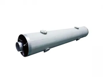
Main Technical Parameter and Dimension
| Rated voltage (KV) | Rated current (A) | BIL(KV) | Dimensions (mm) | Weight Kg/m | |||
| Enclosure фB | Conductor фA | Distance between phases S | Height H | ||||
| Less than 24 | Less than 2000 | 75/150 | ф650 | ф150 | ≥ 900 | 490 | 213 |
| Less than 24 | Less than 2500 | 75/150 | ф700 | ф150 | ≥ 950 | 515 | 222 |
| Less than 24 | Less than 4500 | 75/150 | ф750 | ф200 | ≥ 1000 | 540 | 252 |
| Less than 24 | 5000-8000 | 75/150 | ф750 | ф300 | ≥ 1000 | 540 | 283 |
| Less than 24 | 8000-9000 | 75/150 | ф850 | ф350 | ≥ 1100 | 590 | 316 |
| Less than 24 | 9000-10000 | 75/150 | ф900 | ф400 | ≥ 1150 | 615 | 367 |
| Less than 24 | 10000-14000 | 75/150 | ф1050 | ф500 | ≥ 1300 | 690 | 480 |
| Less than 24 | 20000-24000 | 75/150 | ф1450 | ф900 | ≥ 1800 | 890 | 845 |
| Less than 24 | 24000-26000 | 75/150 | ф1500 | ф950 | ≥ 1900 | 915 | 890 |
| Less than 35 | 27000-30000 | 100/185 | ф1650 | ф1000 | ≥ 2000 | 990 | 980 |
Indexbus duct, electrical busway, busbar system
Links:https://www.globefindpro.com/products/50500.html
-
 Aluminum Bar
-
 Power Distribution Cabinet
-
 Cable Tray
-
 Tin Plated Copper Strip for Photovoltaic
-
 Medium Voltage Cast Resin Busway
-
 Insulated Pipe Busway
-
 Fire Rated Busway
-
 Lighting Control Box
-
 Cereal Corn Flakes Production Line
-
 Pillow Pack Packaging Machine
-
 Sala & Bugles Deep Fry Food Manufacturing Line
-
 Automatic Control Electric Heating Commercial Deep Fryer

