Non-Segregated Phase Bus Duct
The GFM series non-segregated phase busduct is utilized for the circuits of generator sets, main circuits between hydroelectric generators and transformer units. The current range is 1000A~6800A, while the voltage rang is 6.3kV~35kV. The conductor comes in rectangular, U-shaped or tubular copper or aluminum profiles. Aluminum housings provide high quality shielding protection. The cable heat tracer ensures that the internal insulation properties are not affected by external factors, greatly improving stability. The busway system can be equipped with a portable or on-line conductor temperature detection unit to maximize the safety of the entire system.
Ancillary Cabinets and Components
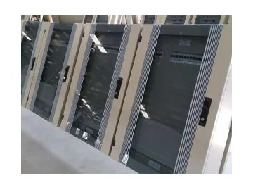
The busduct is outfitted with ancillary cabinets that includes a voltage transformer, lightning arrester, excitation cubicle, neutral grounding resistor, busbar current transformer and other components.
Application of GFM Series Non-Segregated Phase Busduct
GFM Series non-segregated phase bus duct is suitable for transmission systems of 3.6~40.5kV,rated current from 1000 to 6800A, AC 50~60 Hz, which is mostly applied in:
1. The electrical connection between generators and transformers.
2. The electrical connection between transformers and high-voltage distribution cabinets.
3. The electrical connection of AC exciters and rectifier cabinets.
4. The electrical connection of the excitation switchgear and generator rotor ring.
5. The electrical connection between other high voltage main circuits.
Features of GFM Series Non-Segregated Phase Busduct
1. GFM series bus ducts supply consistent strength and low short-circuit ratings. Protected by aluminum or low magnetic plate enclosures, no hysteresis loss occurs on the distribution system. The housing experiences low temperature increases, reducing energy loss on the entire system.
2. When the length of bus duct reaches between twenty and thirty meters, an expansion joint can be installed and adjusted horizontally or vertically in order to offset thermal expansion. This protects the integrity of the whole unit.
3. Flexible braided straps are installed to remove vibration in the connected equipment. Rubber gaskets act as shock absorbers and provide elastic support to the insulator and conductor unit.
4. Moreover, These shock absorber components help prevent damage due to seismic activity.
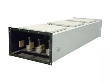
Main Technical Parameters
| Standards | IEC364-5-54/GB/T8349-2000/JB/T9639-1999 | ||||
| Ambient | ℃ | ||||
| Relative humidity | Daily averages ≤ 95%. Monthly average ≤ 90% | ||||
| IP | IP40, IP54 | ||||
| Rated voltage | kV | 3.15 | 6.3 | 10.5 | 35 |
| Max operating voltage | kV | 3.6 | 7.2 | 12 | 40.5 |
| Insulation level | kV | 25/40 | 32/60 | 42/75 | 100/185 |
| Rated frequency | Hz | 50(60) | |||
| Rated operating current | Dimension (W×H)(mm×mm) | ||||
| 1000-3000 | A | I 750×400 II 850×350 | I 900×560 II 1060×460 | I 900×560 II 1060×460 | I 1500×920 II 1800×880 |
| 3500 | A | I 750×440 II 850×480 | I 900×560 II 1060×460 | I 900×560 II 1060×460 | |
| 4000 | A | I 750×440 II 850×480 | I 900×560 II 1060×460 | I 900×560 II 1060×460 | |
| 4500 | A | I 750×440 | I 1000×560 | I 1000×560 | |
| 5000 | A | I 1350×500 | I 1500×600 | I 1500×600 | |
| 6300-6800 | A | I 1350×500 | I 1500×600 | I 1500×600 | |
Note
1. The standard and dimension as above are provided by Wetown.
2. We can provide special designs according to specific requirements.
Indexbus duct, electrical busway, busbar system
Links:https://www.globefindpro.com/products/50525.html
-
 Automotive Precision Mold
-
 MNSH Exchange Low Voltage Switchgear
-
 MLS-V Exchange Low Voltage Switchgear
-
 9 in 1 Multifunction Beauty Machine
-
 980nm Laser Vascular Treatment Machine
-
 KM-L-U300 Lipo Laser Fat Reduction Body Contouring Machine
-
 Insulated Pipe Wind Power Busway
-
 Household Appliance Molds
-
 KYN61-40.5kV Indoor Exchange Metal Switchgear
-
 PV12-12kV Indoor Exchange Metal Switchgear
-
 KYN28A-12kV Open Type Metal Switchgear
-
 Electrical Distribution Box
