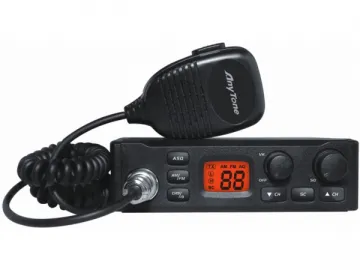
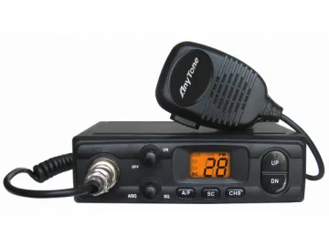
AT-310M Citizen Band Radio
AT-310M citizen band radio can offer available CH9 emergency call channel, SQ function and ASQ function with the frequency range from 25.615 to 30.105MHz. There are various types of channels in our product, including E, D, EU, EC, PL, UK, US and NZ. Besides, its expand mode frequency can be divided into RU type, PO type and PC type.
Note
You might as well joint the antenna to the position of B on the back panel of the radio. Besides, transmitting is not allowed until you set the Standing Wave Ratio, for short as SWR. Otherwise, the power amplifier without guarantee is extremely possible to be damaged.
Welcome to Use
Our citizen band radio possesses best performance, numerous norms and a large amount of function. By adoption of flash CPU in this radio, it is able to carry out future upgrading and function expanding. In order to provide superior quality, high stability and reliability, we apply SMT technology to this product for private communication use or professional use of CB radios. In deed, it is quite necessary for you to take this manual seriously before installing so as to utilize this radio to the deepest extent.
Reset
To reset this citizen band radio, you can switch on the power of the CH9 and CH19 hold key function. In this way, all the channel data will restart the factory default setting.
Installation
1.Where And How To Mount Your Mobile CB Radio
It must be convenient and practical for you to select the most suitable setting, where your citizen band radio will not interfere with the driver or passengers. Thus, you must prepare distinct wires for the passing and protection, such as power, antenna and accessory cabling. Also, you must obtain the cradle and the self tapping screws with the drilling diameter of 4 mm to drill the dash board with no damage to the electrical system of the vehicle. Due to the shock absorbing effect which may cause gentle orientation and tightening of the set, you must insert the rubber joints between the CB and its support. For better sound quality of communication, adding exterior loud speaker is necessary. Besides, you should select the position of the microphone support and make the microphone cord stretch to the driver with no bad influence in the controls of the vehicle. If you have any question about installing this product, you can consult your dealer.
()
2. Antenna Installation
Both mobile antenna and fixed antenna are available and optional for our CB radio, and the longer antenna can lead to the better result. In detail, the mobile antenna can fall into pre regulated type and adjustable type. The former type can be available in good ground plane such as car roof or boot lid, while the latter type serves for smaller ground plane with much larger frequency range. You had better place the mobile antenna to the vehicle away from windscreen mountings with the largest metallic surface or ground plane. Drilling is a must to fix your antenna, and the antenna should be well connected with the ground plane. In prevention of breaking down or short circuiting, pinching or flattening the coaxial cable is not allowed. Moreover, the fixed antenna had better be placed to the most spacious area.
()
:
Output Radius Patterns
3. Power Connection
Power connection is mainly used to guard against the polarity inversion, but you might as well still check all connections before turning it on to ensure that the negative terminal of battery is linked well to the chassis or to the engine block. Furthermore, a continued current of 12 amperes fits into our product.
Notice
Two batteries can be provided by the lorries for 24 volts voltage, so you need to insert a 24/12 volt converter into the electrical circuit. Firstly, you must guarantee the battery of 12 volts. Secondly, you should find the negative and positive terminals of the battery and decide whether to extend the power cable. The cable type must be the same or high class. Besides, the power cable should be directly jointed to the battery to avoid the interference. Then, the black wire must be connected to the negative terminal of the battery, while the red wire is connected to the positive terminal. Finally, you can link the power cable to your product. You might as well know that the original fuse of 5 amperes can not be changed by any distinct value.
()
:
TOwards starter
Connected to chasis
4. Basic Operations
Basic operations include linking the microphone, checking the antenna connections, turning the volume knob clockwise to start the set, turning the squelch knob to the smallest extent, adjusting the volume to a comfortable level, and clicking either the [▲CH ] or[▼CH ] key for channel 20 EC.
5. Adjustment of SWR for StandingWave Ratio
It must be noted that you should make the adjustment in an area without obstacle, and this adjustment should be accompanied with exterior SWR meter. The first step is to connect the SWR meter between the antenna and the CB radio by adoption of 40 cm cable. The SWR meter had better be the closest to the CB radio. Next, you can adjust the SWR meter, including setting the CB to channel 20@EC band in FM, putting the switch on the SWR meter to position CAL or FWD, pressingthe Push-To-Talk switch on the microphone to transmit, utilizing the calibration key to turn the index needle to ▼, and then changing the switch to position SWR. After that, you should adjust the reading on the meter as near as possible to 1, and it is also receivable for the SWR reading between 1 and 1.8. After finishing all the antenna adjustments, you might as well not calibrate the SWR meter again. Finally, you can use your CB.
<!--[if !supportLineBreakNewLine]-->
<!--[endif]-->
Links:https://www.globefindpro.com/products/56523.html
-
 All in One Heat Pump Water Heater
-
 Swimming Pool Air Source Heat Pump
-
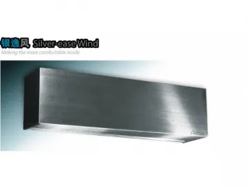 Stainless Steel Air Curtain
-
 Direct Air Source Heat Pump
-
 Ferrari Red Air Curtain
-
 X5 Split Heat Pump Water Heater
-
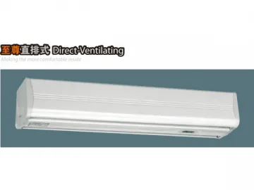 Direct Ventilation Air Curtain
-
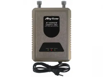 AT-4100GW Dual Band Mobile Repeater / Signal Booster
-
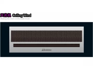 Ceiling Air Curtain
-
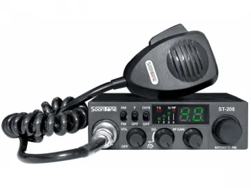 AT-208 Citizen Band Radio
-
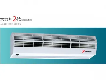 Titan 2 Super Thin Air Curtain
-
 AT-300M Citizen Band Radio