Process Control
Step 1 Transformer Oil
Charge (who is in charge): worker, leading technician
Table and title: work report, test report
| Critical Control Point | Control Method |
| Oil Temperature | Oil temperature at oil filter’s outlet≤ 85 °C |
| Residual oil, new oil | Tests residual oil, new oil or the combination of the two. |
| Micro water content in transformer oil | 500kV/10ppm; 220~330kV/15ppm; 110kV/20ppm; Residual oil ≥30ppm |
| Dielectric strength | 500kV/60kV; 330kV/50kV, 220~63kV/40kV |
Step 2: Nitrogen Removal
Table and title: Work report, inspection table
Charge: worker, group leader, or technician
| Critical Control Point | Control Method |
| Oil injection | Make sure residual oil has drained off. Oil is injected from the bottom of the transformer tank (so nitrogen exits the tank from the top). After transformer oil totally fills the tank, decrease the oil level gradually to 100mm to 200mm from the top. Maintain that oil level for 12 hours. |
| Vacuum pumping | A vacuum pump is used to fill the tank with dried air. This process should be done in line with GDJ148-90 requirements. |
| Dry Air Generator | Micro-water content in dry air at the outlet of the air generator: ≥150 ppm |
Step 3: Iron Core
Table and title: Iron core inspection report, commissioning report
Charge: technician, field operation supervisor, quality inspector, safety supervisor, commissioner, factory worker, representative from Party A, on-site inspector
| Critical Control Point | Control Method | |||||
| Air exposure time | Relative Humidity: 75%/16h, Ambient Temperature: ≤ 0°C, Transformer temperature increase ≥10°C | |||||
| Transformer cabinet inspection | Steel wire ropes used to lift the transformer housing must meet related requirements. | |||||
| Mechanical Tap Changer | Air exposure time | Ambient Temperature | > 0 °C | > 0 °C | > 0 °C | < 0 °C |
| Relative Humidity /Hours | <60%/24h | 65 ~75%/16 h | 75 ~85%/10 h | 8 h | ||
| Internal gear | All gears run smoothly without abnormal sound or stuck gear teeth. Shaft retainers are complete and in place. | |||||
| Contact Resistance | Electrical contacts at each tap position need to be checked against related standards. | |||||
| Seal | Tap changer compartment is bolted tightly by anchor bolts. Flange seals are provided. | |||||
Other Inspections
| Items for Inspection | Fasteners, insulating supports, and insulating boards are intact and secured tightly in place. Exposed leads and bus bars are welded tighter. The weld should be burr-free. Transformer body is in the place where it is supposed to be. The dielectric strength and spatial arrangement of insulating components and conductors meet related regulations. The electrostatic shield is intact and held tightly in place. Rotating disks of the butterfly valve are free of clog and void. O-ring seals are reliable. |
| Iron Core Check | Make sure there is only one point connected to ground.Iron core yokes, clamps, reinforcement stems, electrostatic shield, pressure plates, and pressure plate bolts are well insulated. |
| Transformer Winding | Winding insulations and supports are intact and complete. Oil supply line is clog-free. Locknuts are used on the pressure plate bolts to ensure reliability.Leads are wrapped in protective covers, and no fraying or twisting occurs. |
Step 4: Parts Assembly
Report table and title: inspection table
Charge: worker, group leader, technician, commissioner
| Critical Control Point | Control Method |
| Conservator | Conservator tank is completely sealed and tank bladder is intact without damage. Tank valve operates freely and is sealed tightly. Oil level gauge is calibrated to display accurate readings. Make sure the oil level is maintained at a proper level and there is no residual gas inside the tank after the gauge is installed. |
| Cooler | Cooling system is tightly sealed. Buchholz relay operates properly. Blower motor and oil pump motor are well insulated. Make sure residual gas drains off completely. Electrical controls meet related standards. Power supply cabinet is protected against moisture. |
| Pipes, Transformer Tank | Please do remember to remove the temporary caps on the pipes before connecting different pipe sections. Pipe inside should be clean. Flange weld seam should be void-free. Pipes are free of cracks. Valves on main pipeline can operate freely and are marked clearly to show their exact location. Transformer tank, pipe line and blind flanges are sealed properly. O-rings can be squeezed to a maximum of more than 1/3 of their thickness. |
| Primary, Secondary Transformer Gas Relay | Gas relays should be installed horizontally. Spouts should be directed away from the tank.Prior to installation, all gas relays need to be inspected by a third-party auditor. Each gas relay should be presented with test report and certificate. |
| Raised Base | Current transformer tests. Output terminal block is well insulated, fastened, and sealed tightly against leaks. Nameplate is in place. The exhaust plug should be placed at the top of the raised base. Coils and insulating supports are in the right place and well insulated. |
| High and Low Voltage Bushings | High and low voltage bushings do not allow oil penetration. Oil level indicator is installed outside the tank. A proper oil level should be maintained. Ceramics are clean and without damage. Winding leads are covered with bushings and well sealed. Electrical ground is available. |
| Temperature Gauge | The temperature gauge needs calibration before installation. |
Step 5: Vacuum Oil Pumping
Report table and title: inspection table
Charge: worker, group leader
| Critical Control Point | Control Method |
| Vacuum inspection | 500kV ≥ 4h; 220~330kV ≥ 8h |
| Oil pumping | Oil flow speed ≤ 100L/min, oil temperature at oil filter’s outlet ≥85°C, vacuum duration after oil pumping: 220kV ≥ 4h; 110kV ≥ 2h |
Scan QR to Read
Links:https://www.globefindpro.com/products/58765.html
Links:https://www.globefindpro.com/products/58765.html
Recommended Products
-
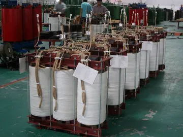
 Carbon Steel Plate and Sheet Processing
-
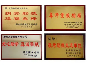 Social Contribution
-
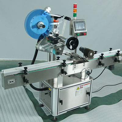
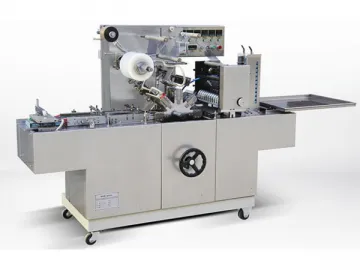 Cellophane Overwrapping Machine, BTB-300A
-
 Honeywell Life Safety (Nantong) Co., Ltd.
-
 Datang NXP Semiconductors Co. Ltd.
-
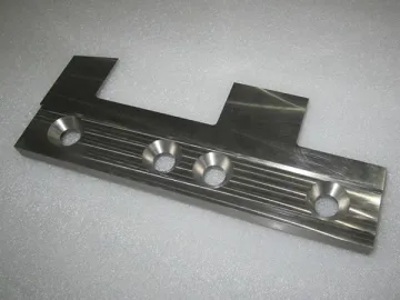
 Parts for Aerospace Industry
-
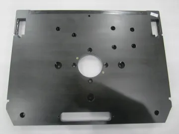
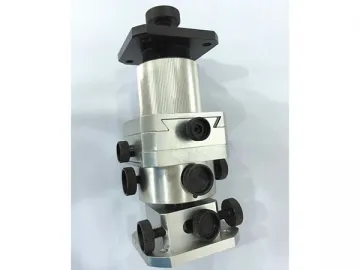
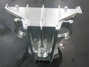
 Engineering Machinery Parts
-
 Heat Shrinkable Tubing Workshop
-
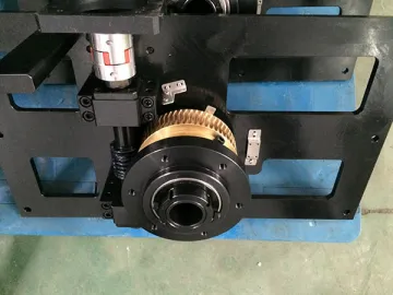
 Robot Parts
-
 Non-Standard Equipment
-
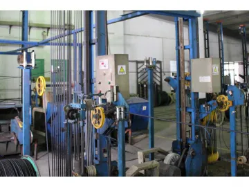
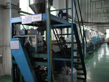 Monofilament Extruding Workshop
-
 Medical Parts
Hot Products