Servo System for CNC Machine Tool
Abstract
This article gives customers from machining industries a typical example of using servo system to provide precise machine tool motor control. As operators perform precision machining on shafts or other parts with complex geometries, our servo system delivers the exceptional motor control performance needed to get the machining work done fast to high quality standards.
Foreword
The demand for higher-precision parts with better surface finish has led to a growing emphasis on more precise machine tool motor control. In particular, the NC lathe is now having a more critical role to play than ever in automobile, power generation, shipping, metallurgical, military, and aerospace industries. The level of automation somehow determines the machining efficiency and capacity of your lathe. When it comes to industrial automation, our servo system is among the best-in-class motor control products available on the market worldwide.
We are experienced in modifying machine tools using advanced servo motor and servo drive. Our servo system is quite competitive in terms of either performance or price. To compete in today’s machine parts industry, customers need such high-quality servos to ensure machining precision and efficiency. Traditional servo systems use either PWM controller or serial bus controller for motor control. Unlike conventional control methods, our modified pulse controller is sure to bring more motion regulation precision.
Pictured below shows a machine tool in action.
Wiring
Pulse controller is easy to install, requiring very simple wiring. It needs less inputs and outputs than a serial bus controller which requires frequent data exchange. A point-to-point connection is established between the controller and NC operation panel.
This servo system does not use the fiber Bragg grating sensor to form a closed loop control system. Rather, the system is often thought of as a semi-closed control loop that has an incremental encoder installed on the motor. Position control is possible via sending pulse direction signals. The servo drive can be directly connected to the power grid or, in order to get rid of low-frequency interference signals or prevent the impact of 3-phase imbalance on the equipment, has a 3AC 380V/3AC 220V isolation transformer fitted between the drive and power grid. Pictured below shows the wiring, which connects the servo system to the CNC machine tool.
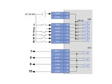
1. Servo enable, alarm clearance
2. clockwise drive restricted
3. counter-clockwise drive restricted
4. error calculator reset
5. commanded pulse prohibited
6. servo ready, servo alarm
7. motor braking output
8. DG output common port
1. Position command PULS (pulse)
2. Position command SIGN (orientation)
3.metal casing for CN1 terminals
Parameter Settings
| X-Axis | Z-axis | ||
| PA5 | 150 | PA5 | 150 |
| PA7 | 256 | PA7 | 256 |
| PA8 | 128 | PA8 | 128 |
| PA9 | 40 | PA9 | 40 |
| PA12 | 5 | PA12 | 5 |
| PA13 | 4 | PA13 | 3 |
Links:https://www.globefindpro.com/products/60350.html
