Crossed Roller Bearing
1. Description
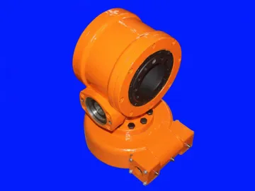
The XR series crossed roller bearing is characterized by high stiffness, low friction torque, and compact structure. When the four-point contact ball bearing fails to meet customer's requirement on torque and stiffness, the XR series slewing bearing ring is a good choice.
2. Features
There is a V-shaped raceway in the ring and cylinder rollers are used. The rollers are arranged in cross, which enables the crossed roller bearing to bear radial force, axial force, and torque load or mixed load. Compared with the four-point contact ball bearing, our crossed roller bearing has lower rotation resistance moment since each roller only bears the load in one direction and the roller is able to provide higher rigidity than the ball due to its contact area and geometric shape.
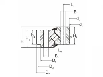
In case of the same size, roller has higher bearing capacity than ball. However, since not all rollers point to the same direction, the crossed roller bearing is inferior to the four-point contact ball bearing in resisting thrust and torque load.
Gear or other driving mechanism can be designed on the inner or outer ring. In addition, the hole form for the slewing bearing can be specified by the customers.
3. Supply Capacity
This series of slew ring bearing is customized, so customer's requirements can be well satisfied.
4. Application
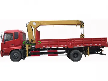
The crossed roller bearing is widely used in occasions requiring high stiffness and low torque, such as radar, excavator, machine tool, military turret, etc.
5. Technical Parameters of the Cylindrical Roller Bearing
| No Gear | ||||||||||||||||||||||||
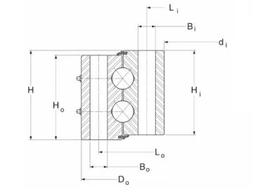
| P/N | OUTLINE DIMENSIONS AND WEIGHT | HOLE DATA | GEAR DATA α = 20° | GEAR TOOTH RATING Fz | DYNAMIC CAPACITIES 1 MILLION REVOLUTIONS L10 LIFE | |||||||||||||||||||
| OUTER RING | INNER RING | |||||||||||||||||||||||
| Do | di | H | Ho | Hi | Dr | dr | G APPROX. | Lo | no | Bo | Li | ni | Bi | TOOTH FORM | D2 | Pd or(m) | z2 | x2 | b2 | RADIAL | THRUST | MOMENT | ||
| (in) | (in) | (in) | (in) | (in) | (in) | (in) | (lbs) | (in) | (in) | (in) | (in) | (in) | (in) | (lbs) | (lbs) | (lbs) | (ft-lbs) | |||||||
| 16318001 | 11.811 | 5.512 | 1.417 | 1.181 | 1.181 | — | — | 30 | 10.630 | 6 | M16×2 | 6.693 | 6 | M16×2 | — | — | — | — | — | — | — | 19,150 | 22,340 | 7,530 |
| 16319001 | 15.886 | 9.055 | 2.165 | 1.772 | 1.850 | — | — | 65 | 14.094 | 24 | 0.512 | 10.197 | 24 | 0.512 | — | — | — | — | — | — | — | 36,850 | 42,830 | 20,140 |
| 16320001 | 27.362 | 18.779 | 3.031 | 2.520 | 2.244 | 27.283 | 18.897 | 185 | 25.197 | 28 | 0.709 | 20.000 | 28 | 0.709 | — | — | — | — | — | — | — | 64,560 | 73,730 | 65,660 |
| 16321001 | 35.312 | 26.625 | 2.953 | 2.863 | 2.863 | 35.251 | 26.750 | 325 | 34.000 | 24 | 1/2-13 | 29.000 | 24 | 0.590 | — | — | — | — | — | — | — | 81,310 | 91,980 | 116,170 |
| 16322001 | 46.250 | 34.250 | 4.250 | 3.880 | 3.880 | — | 34.380 | 765 | 44.000 | 28 | 1-8 | 36.250 | 28 | 1.063 | — | — | — | — | — | — | — | 235,420 | 270,010 | 425,900 |
| 16323001 | 56.380 | 46.770 | 3.820 | 3.470 | 3.430 | 56.295 | 46.850 | 710 | 40.000 | 36 | 0.813 | 33.875 | 36 | 3/4-16 | — | — | — | — | — | — | — | 209,680 | 237,380 | 482,960 |
| 16324001 | 85.000 | 74.000 | 3.750 | 3.250 | 3.250 | 84.880 | 74.120 | 1,190 | 83.000 | 42 | 0.938 | 76.000 | 42 | 0.938 | — | — | — | — | — | — | — | 267,330 | 300,410 | 956,430 |
| 16325001 | 95.000 | 82.000 | 4.000 | 3.500 | 3.500 | 94.875 | 82.063 | 1,660 | 93.000 | 48 | 1.063 | 85.000 | 48 | 1.063 | — | — | — | — | — | — | — | 362,100 | 407,250 | 1,450,300 |
| 16326001 | 131.890 | 112.205 | 7.874 | 6.496 | 7.087 | 131.250 | 120.866 | 6,500 | 127.559 | 40 | M36×3 | 116.535 | 40 | 1.496 | — | — | — | — | — | — | — | 762,050 | 858,130 | 4,185,500 |
| 16327001 | 158.661 | 140.945 | 8.819 | 6.654 | 6.654 | — | — | 6,400 | 155.315 | 92 | 1.654 | 144.291 | 92 | 1.654 | — | — | — | — | — | — | — | 723,870 | 812,130 | 4,879,900 |
Links:https://www.globefindpro.com/products/60561.html
