VFD Working Principle
Working Principle of Variable Frequency Drives
Our medium voltage variable frequency drive (VFD) adopts the multi-level cascaded power unit technology to obtain medium voltage directly by means of overlap wave. The low voltage power unit is actually an improved motor variable frequency drive, which takes full advantage of mature technology. Our VFD adopts a voltage source inverter. Users can apply medium voltage (3/3.3/4.16/6/6.6/10/11KV) directly to the input terminal of the VFD, and then the VFD outputs medium voltage (3/3.3/4.16/6/6.6/10/11KV) correspondingly, needing no output step-up transformer.
| Voltage level (kV) | Cell quantity for each phase | Output phase voltage (V) | Output line voltage (kV) | Pulses | Number of voltage level for each phase |
| 3/3.3 | 3 | 1732 | 3 | 18 | 7 |
| 4.16 | 4 | 2401 | 4.16 | 24 | 9 |
| 6 | 5 | 3450 | 6 | 30 | 11 |
| 6.6 | 6 | 3810 | 6.6 | 36 | 13 |
| 10 | 8 | 5770 | 10 | 48 | 17 |
| 11 | 9 | 6351 | 11 | 54 | 19 |
For different voltage output, the quantity of power units is different, but the working theory is exactly the same. All power units receive instructions from the same central process controller. There is a phase difference between the secondary windings of the transformer providing energy to power units. In this way, most of the harmonic current produced by the independent power unit will be eliminated, so the primary winding current is approximately sine wave. Few harmonic current will flow into the power grid. Even under the rated load, the harmonic current content is as low as 3%.
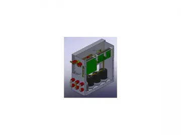
The power unit of our variable frequency drive is AC-DC-AC in structure, equivalent to a low-voltage power inverter of 3-phase input and single-phase output. The rectifier side is diode three-phase full-bridge circuit. Single-phase AC can be output by the IGBT inverter bridge controlled through sine PWM mode. All power units are exactly the same in structure and in electrical performance, so maintenance and replacement are very easy.
Power Cell Structure
Links:https://www.globefindpro.com/products/61965.html
-
 TSC Principles
-
 CJI430S 3D Blu-Ray DVD Player
-
 TBBPA Carbonate Oligomer BC52, FR-52
-
 QHD Series Disposable Linear Cutter Stapler
-
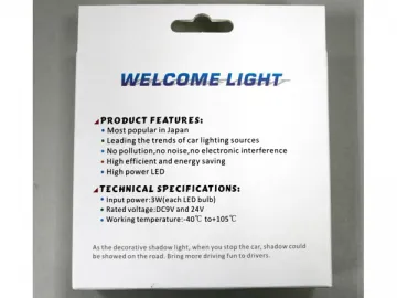 Car Welcome Light
-
 CJI2014A Wireless Home Theater
-
 Car Charger
-
 Potassium, 3-Phenylsulfonyl Benzenesulfonate
-
 M9 Spinal System Instrument Set
-
 Data Analysis and Conclusion
-
 FHD Series Reusable Linear Stapler
-
 Working Principle
