TSC Principles
Thyristor Switched Capacitor Principles
Thyristor switched capacitor bank (TSC/TSF) is a kind of reactive power compensation equipment based on the switching operation of thyristor. It is mainly composed of control system, thyristor, capacitors and reactors. TSC is divided into multiple units to realize step-by-step regulation of reactive power, and the accuracy of regulating depends on the number of the units.
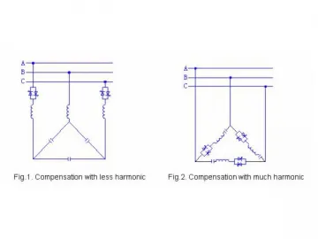
Our thyristor switched capacitor banks adopt delta wiring. Its capacity and branch configuration are designed according to reactive power variation and harmonic components from nonlinear load so as to optimize effect of reactive power compensation and harmonic filtering.
Topological Graph
Delta Connection Three-Phase Compensation
| Fig.1. Compensation for less harmonic Fig.2. Compensation for much harmonic |
Star Connection (≥690V power system)
| Fig.3. Compensation for much harmonic Fig.4. Compensation for less harmonic |
Control Modes
Our thyristor switched capacitor bank is controlled by the fast fluctuant load directly or by the demand of reactive power dynamically.
1. Load-Controlled Capacitor Banks
A high-power machine with highly variable loads, such as the welding machine, will cause voltage drop in the supply system. The quantity of such a drop depends on the output power of the machine and on the short-circuit power of the distribution network (see Fig.1). A drop in the secondary voltage is reflected in the primary voltage, causing the quality of the distribution voltage to deteriorate everywhere in the transformer circuit.
The effects of a voltage drop in a distribution network are proportional to the amount of the drop and to the frequency of its occurrence. A thyristor-switched capacitor bank significantly suppresses these effects and ensures that the distribution voltage meets the standards.
Supporting and stabilizing the supply voltage, a TSC reduces the energy consumption of the production equipment and thus increases their capacity.
Control signals should be sent from the high-speed welding machine to the capacitor banks directly, so as to achieve the best possible results in the power factor correction of the machine.
The required power factor correction is given by:
Q = SK×ΔU(%)
Where,
U-voltage drop at load connecting point
SK-short-circuit capacity at load connecting point
Q-required power factor correction
2. Capacitor Banks Controlled by Reactive Power
Thyristor-switched capacitor banks are able to quickly correct power factor of machines with rapidly changing loads, such as lift and crane drives. Using thyristors instead of contactors yields faster switching and saves the work caused by maintenance and replacement of contactors which wear rapidly.
The control system switches the capacitor bank steps on and off according to the demand of reactive power. The control is based on a kind of "first-in last-out" principle: the first step is switched on first and switched off last. Our company has developed the unique fuzzy control switching theory and realized that the minimum time the control system needs to switch all the steps of the capacitor bank on or off is as short as one network period.
Links:https://www.globefindpro.com/products/61966.html
-
 CJI430S 3D Blu-Ray DVD Player
-
 TBBPA Carbonate Oligomer BC52, FR-52
-
 QHD Series Disposable Linear Cutter Stapler
-
 Car Welcome Light
-
 CJI2014A Wireless Home Theater
-
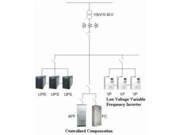 Compensation Mode Selection
-
 VFD Working Principle
-
 Car Charger
-
 Potassium, 3-Phenylsulfonyl Benzenesulfonate
-
 M9 Spinal System Instrument Set
-
 Data Analysis and Conclusion
-
 FHD Series Reusable Linear Stapler


