SVC System Configuration
SVC System Configuration (Static VAR Compensator)
A. Control System with High-Speed Response
The control system of our SVC adopts microelectronic and full digital chip to monitor power quality data in real time. It can dynamically output corresponding reactive power the load wants through high-speed calculation. It uses advanced AC waveform analysis technology to ensure accuracy of parameter setting and stability of operation even under severe power conditions, such as strong interference, high harmonics, etc.
The controller is provided with a LCD as well as RS485 and RS232 communication interfaces. It has the functions of monitoring, control, data backup, check and data conversion storage. It can also carry out real-time analysis for current, voltage, active power, reactive power, and reactive current of the compensation devices and harmonic filtering system. In addition, the controller has many protective functions, such as protection against over-voltage, under-voltage, over-current, external access faults, inner faults, voltage sampling lost, three-phase current unbalance, and so on.
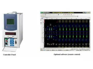
The optional operating software has visual system circuit displaying and operating interface. It can display three-phase reactive power, three-phase active power, current, power factor, working state of MCR type SVC, desired power factor and set value, which helps realize remote monitoring and communication regulation.
B. Magnetically Controlled Reactor
Our SVC adopts saturated iron core reactor which is connected in parallel to high voltage main circuit to provide inductive reactive power. There are two kinds of reactors for selection. One is dry-type reactor with epoxy resin and the other is oil-immersed reactor. They both have the advantages of small size, low noise and low harmonics.
C. Low Voltage SCR Module
Our static VAR compensator adopts mature low voltage SCR triggering technology and rectification modules. The triggering mode is phase-shift trigger. The complex programmable logic device adopted has simple circuit and high accuracy, ensuring safety and reliability of the system.
The closed-loop control system adjusts the DC excitation current of the magnetically controlled reactor precisely to change the impedance of MCR smoothly, thus realizing high-speed dynamic reactive power compensation. The thyristors are imported from abroad; trigger circuit is isolated by optical fiber, and the high voltage circuit is also fully isolated from the low voltage circuit by high voltage insulation optical cable, so the operation is very safe and stable.
The adoption of advanced BOD protection module enhances the operation safety of the equipment, and the fault self-lock protection function makes it safer to use. Additionally, the small-sized low voltage thyristors generate low heat, so there is no need of any cooling devices.
D. FC Capacitor Branch Circuits (capacitive reactive power and harmonic compensation)
The FC capacitor circuit consists of capacitor, series reactor and resistor used in high-pass filter branch. It can be divided into 2nd, 3rd, 4th, 5th, 6th, and other higher-order harmonic passage according to system requirement, and it can compensate capacitive current of fundamental wave. In addition, it can realize dynamic reactive power compensation of the system through combination with MCR.
Links:https://www.globefindpro.com/products/61984.html
-
 Tetrabromophthalic Anhydride, TBPA
-
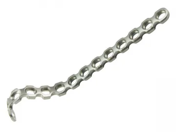 Distal Medial Humeral Plate
-
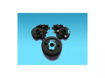 Decabromodiphenyl Ethane, DBDPE
-
 Tris, tribromophenyl Cyanurate / JHFR-245
-
 TBBPA Carbonate Oligomer BC58, FR-58
-
 Clavicle Hook Plate/Clavicular Plate
-
 Y-Distal Humeral Y-Plate II
-
 CJI7700 Wireless Home Theater
-
 CJI09A Wireless Home Theater
-
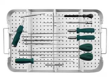 M6 Spinal System Instrument Set
-
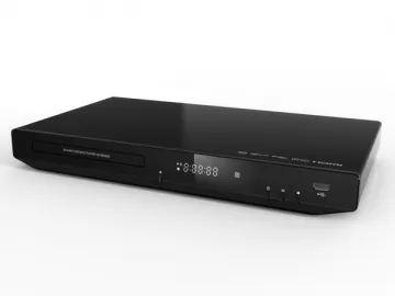 CJI360S Blu-Ray DVD Player
-
 VFD Structure
