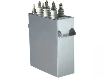
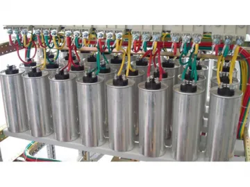
Induction Heating Capacitor
General Description
The induction heating capacitor is mainly used in the inductive heating system to increase power factor or improve circuit characteristics. The performance of RWM and RFM types of water-cooled style and full-film product conform to JB7110-93, "Capacitor for Electric Heating Installations", and IEC 60110 (1998), "Capacitors for Inductive Heat Generating Plants Operating at Frequencies between 40Hz and 24000Hz".
Service Conditions
1. Indoor use;
2. Altitude≤ 1000m
3. No violent mechanical vibration, no harmful gas or vapor, and no explosive dust at the installation site
4. Temperature of ingoing cooling water ≤ 30℃; ingoing water flow for capacitor with capacity less than 1000kvar ≤ 4L/min; for 1000kvar or more ≤ 6L/min.
5. Long-term over-voltage: ≤ 1.1Un, less than 4 hours within 24 hours; Long -term over-current: ≤ 1.35In, including harmonic current.
Related Names
High Capacity Capacitor | Electric Capacitor | Solid State Capacitor
Model Description
Note
1. The first letter R indicates capacitor for electric induction heating system.
2. Second letter W (or F) represents the impregnating agent for benzene (or diphenylethane).
3. The third letter M represents the whole film medium.
4. S represents Water-cooled.
5. “2” – design number is expressed as steel shell electric capacitor.
Applications
The induction heating capacitor is mainly used in AC power systems with the rated voltage of 3.6KV or less and the frequency of 40Hz to 24,000Hz. It is designed to improve induction heating, melting or casting stirring devices, and similar applications where power matters.
Structural Characteristics
The electric capacitor is constructed from following main components:
1. Border
Capacitor elements are made from capacitor paper and aluminum plate. Elements are prominent in the extra cellular medium plate, a plate on which a cooling water pipe is welded. The total head for the plate is a connection of cooling water pipe and a ground stud or ground cover sheet.
2. Plate
The second plate is insulated from the shell, connecting gusset and guide rod, and drawn by porcelain lid.
3. Shell
Shell of the induction heating capacitor is a rectangular box, which is welded on both sides of the tank wall. It has no cover configuration and grounding rods or ground lug stud.
Technical Performance and Requirements
1. Capacitance Tolerance
-5% to 10%; the difference between the maximum and minimum capacitance is not more than 1.1.
2. Dielectric Loss Tangent Tan (the whole film medium) at rated voltage UN and 20℃:
A. UN≤1KV: Tanδ≤0.0015
B. UN>1KV: Tanδ≤0.0012
3. Dielectric Strength
Between the terminal and the casing can withstand the power frequency test of 1KV in 1 minute.
4. Cooling water inlet temperature does not exceed 30℃.
A. QN≤1000KVAR capacitors; water flow ≥4L/MIN
B. QN≥1000KVAR capacitors; water flow ≥6L/MIN
5. Long-running over-voltage (24H does not exceed 4H) can not exceed 1.1UN.
6. Long-running over-current (including harmonic current) can not exceed 1.35LN.
7. Indoor installation altitude does not exceed 1000M.
8. Ambient air temperature in installation and operation area does not higher than 50℃.
9. During installation and operation, there should be no corrosive gases and vapors as well as non-conductive or explosive dust and severe mechanical vibration.

Links:https://www.globefindpro.com/products/62229.html
-
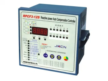 RPCF3 Series Automatic Three Phase Reactive Power Compensation Controller
-
 Low Voltage Series Reactor
-
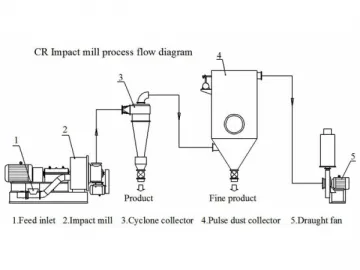 Superfine Impact Mill
-
 PU3500&4500 Industrial Energy Saver
-
 JK-8CK(H) Series Intelligent Low Voltage Reactive Power Compensation Controller
-
 BGMJ Series Low Voltage Shunt Capacitor, Power Capacitor
-
 CJ19 Series AC Capacitor Switching Contactor
-
 JHM Ball Mill
-
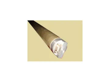 High Temperature Lithium Battery Sleeve
-
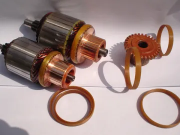 High Strength Insulating Ring
-
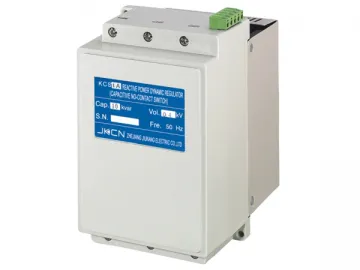 Non-Contact Switch for Shunt Capacitor
-
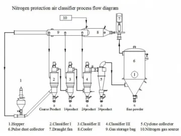 Air Classifier