Slewing Bearing Installation and Maintenance
Packaging and Transportation
Before packing, the slewing bearing has to be coated with antirust lubricating grease on the inner and outer raceway. Then it will be wrapped with plastic film, composite kraft paper and industrial wrapped tape for inner package. Its outer package uses specialized wooden case or iron case.
The slewing bearing shall be placed on the flat surface horizontally as could as possible during the transportation to prevent impact and severe vibration. After opening the package, the eyebolts will be screwed on the holes for hoisting on inner ring or outer ring, lifting the product to the installing position.
Storage
a. Before use, the package is prohibited to be unfolded during rustproof period, which is about 12 months after leaving the factory. If the package is broken or the product needs to be stored over the rust resistant period, users should clean it again and adopt the antirust treatment.
b. The slewing bearing is required to be stored in the dry, ventilated and flat places horizontally, kept away from the chemicals and other corrosive objects. For several sets of products piled together, users should put at least three wooden cushion blocks with equal height evenly along the circle direction between each two sets of products. Moreover, the upper layer wooden block should be placed in the consistent position with the lower one. If the bearing still needs storing over antirust period, it should be cleaned and anti-rusted again.
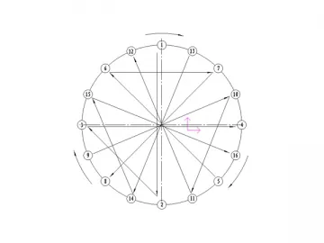
Usage & Maintenance
1. Inspection for the mounting bolts and abnormal situations
a. After the first 100 hours of operation, the pre-tightening torque of the mounting bolts on inner and outer tracks shall be checked. The bolts need inspection every 500 hours at least in the later operating to keep enough preload force.
b. If it appears noise, impact, abrupt power increase and other abnormal phenomenon on the slewing bearing, the machine should be stopped for checking and eliminating the faults, as well as overhauling if necessary.
c. The sealing part of the product needs to be inspected frequently and the damaged one should be changed in time. It should be reset if the sealing part falls off.
2. Lubrication
a. The bearing leaving factory is filled with a little No.2 lithium-based grease in the raceway. According to different working conditions, it needs new lubricating grease for filling while using.
b. After mounting, the slewing bearing should be lubricated with suited grease on the basis of actual working conditions. The grease will be injected evenly over rotating the product till the new grease is extruded from the sealing lips. The bearing needs greasing every 50 hours to 100 hours. The greasing cycle should be shortened under the condition of high temperature or in the dusty environment. Before the machine stops working for a long time or starts working again, enough grease should be filled.
3. Cleaning and lubricating for the gear surface
Take strict precautions against the hard foreign materials approaching or entering the gear engagement area. The gear surface needs cleaning and plating with lubricating grease every 10 days.
4. Selection of lubricating grease
In different working conditions, the selection of grease is referenced in Table 4.
Table 4
| Slewing bearing | Working condition | Lubricate position | Lubricating grease | |||
| Grease name | Trademark | Standard | ||||
| Rubber seal with plastic spacer | Low and normal temperature, humid-40℃~60℃ | Raceway | Calcium-based grease | ZG-3 | GB491 | |
| ZG-4Z | ||||||
| G-5 | ||||||
| Gear | graphite calcium grease | ZG-S | SY1405 | |||
| Labyrinth seal with metal spacer | High temperature and humid | 40℃ ~140℃ | Raceway | Lithium-based grease | ZL-1 | Q/SY1002 |
| ZL-2 | ||||||
| MoS2 calcium complex grease | No 3 | |||||
| Gear | No. 4 High- temperature grease | ZN6-4 | GB491 | |||
| 80℃ ~180℃ | Raceway | MoS2 calcium complex grease | No 2 | |||
| Gear | No. 4 High- temperature grease | ZN6-4 | GB491 | |||
| Normal temperature, seawater corrosion resistance ~50℃ | Raceway | No. 2 aluminum-based grease | ZU-2 | SYB1408 | ||
| Gear | No. 3 aluminum-based grease | ZU-2 | SYB1408 | |||
Note: Due to various comprehensive factors for working conditions, users can choose the optimal grease by themselves based on the specific requirements.
Abrasion Limit of Slewing Bearing Raceway
1.Initial clearance
The initial clearance of the bearing is a compensation for geometry accuracy between the product and mounting plane within the allowable tolerance range. It is suitable for normal working condition at normal temperature. Therefore, this compensation is assumed to be used up when the abrasion limit is taken into consideration. It means the clearance of the product is zero.
2. Method of measuring the raceway abrasion loss
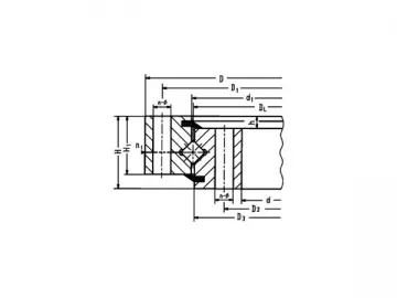
The abrasion loss of raceway in the bearing can be confirmed through measuring the variation of "e" value, which expresses the relative axial position of inner and outer rings. The detailed methods are described as follows. (Refer to Figure A)
a. Every slewing bearing leaves the factory with different "e" value. After installation, the "e" value should be measured and kept on file.
b. With the raceway wear of the product during operation, users need to check the decrease of "e" value regularly, △e that means the difference between initial clearance and new measurement value.
3. Influence of "e" value variation on the performance of the slewing bearing
As "e" value declines to certain value, the bearing will work in the unsafe situation and the new one shall be replaced. If the product undertakes tilting moment after severe wear, there will be relative movement against the mounting plane happening to the inner and outer rings, which will rub directly sometimes. Due to the reduction of the raceway hardened layer, the load capacity of the product reduces enormously even though the tilting moment is small. It is necessary to change a new one.
4. Variation of "e" value for slewing bearing is showed in the following tables.
Maximum Allowable △e Value of Double Row Ball Slewing Bearing (mm)
| Roller balldiameter Max. △e value | 18 | 20 | 22 | 25 | 30 | 35 | 40 | 45 | 50 | 60 | 70 | |
| Tracking diameter (mm) | ||||||||||||
| ~ | 1000 | 1.8 | 1.8 | 1.9 | 1.9 | 2.0 | 2.1 | 2.5 | 2.8 | |||
| 1000 | 1250 | 1.9 | 1.9 | 2.0 | 2.0 | 2.1 | 2.2 | 2.6 | 2.9 | 3.4 | 3.6 | |
| 1250 | 1500 | 2.0 | 2.1 | 2.1 | 2.2 | 2.3 | 2.7 | 3.0 | 3.5 | 3.7 | ||
| 1500 | 1750 | 2.2 | 2.2 | 2.3 | 2.4 | 2.8 | 3.1 | 3.6 | 3.8 | 4.0 | ||
| 1750 | 2000 | 2.3 | 2.4 | 2.5 | 2.9 | 3.2 | 3.7 | 3.9 | 4.1 | |||
| 2000 | 2250 | 2.5 | 2.6 | 3.0 | 3.3 | 3.8 | 4.0 | 4.2 | ||||
| 2250 | 2500 | 2.7 | 3.1 | 3.4 | 3.9 | 4.1 | 4.3 | |||||
| 2500 | 2750 | 2.8 | 3.2 | 3.5 | 4.0 | 4.2 | 4.4 | |||||
| 2750 | 3000 | 3.3 | 3.6 | 4.1 | 4.3 | 4.5 | ||||||
| 3000 | 3250 | 3.4 | 3.7 | 4.2 | 4.4 | 4.6 | ||||||
| 3250 | 3500 | 3.5 | 3.8 | 4.3 | 4.5 | 4.7 | ||||||
| 3500 | 3750 | 3.6 | 3.9 | 4.4 | 4.6 | 4.8 | ||||||
| 3750 | 4000 | 4.0 | 4.5 | 4.7 | 5.0 | |||||||
| 4000 | 4500 | 4.2 | 4.7 | 4.9 | 5.2 | |||||||
| 4500 | 5000 | 4.9 | 5.1 | 5.4 | ||||||||
| 5000 | 5500 | 5.1 | 5.3 | 5.5 | ||||||||
| 5500 | 6000 | 5.3 | 5.5 | 5.7 | ||||||||
| 6000 | 6500 | 5.7 | 5.9 | |||||||||
| 6500 | 7000 | 5.9 | 6.1 | |||||||||
| 7000 | 7500 | 6.3 | ||||||||||
| 7500 | 8000 | 6.5 | ||||||||||
Maximum Allowable △e Value of Single Row Ball Slewing Bearing (including four-point contact ball type) (mm)
| Roller ball diameterMax. △e value | 20 | 22 | 25 | 30 | 35 | 40 | 45 | 50 | 60 | 70 | |
| Tracking diameter | |||||||||||
| ~ | 1000 | 1.4 | 1.4 | 1.4 | 1.5 | 1.7 | 1.9 | 2.1 | 2.5 | ||
| 1000 | 1250 | 1.5 | 1.5 | 1.6 | 1.7 | 2.0 | 2.2 | 2.6 | 2.7 | ||
| 1250 | 1500 | 1.6 | 1.7 | 1.7 | 2.0 | 2.3 | 2.6 | 2.8 | |||
| 1500 | 1750 | 1.7 | 1.8 | 2.1 | 2.3 | 2.7 | 2.9 | 3.0 | |||
| 1750 | 2000 | 1.8 | 1.9 | 2.2 | 2.4 | 2.8 | 2.9 | 3.1 | |||
| 2000 | 2250 | 2.0 | 2.3 | 2.5 | 2.9 | 3.0 | 3.2 | ||||
| 2250 | 2500 | 2.0 | 2.3 | 2.6 | 2.9 | 3.1 | 3.2 | ||||
| 2500 | 2750 | 2.4 | 2.6 | 3.0 | 3.2 | 3.3 | |||||
| 2750 | 3000 | 2.5 | 2.7 | 3.1 | 3.2 | 3.4 | |||||
| 3000 | 3250 | 2.6 | 2.8 | 3.2 | 3.3 | 3.5 | |||||
| 3250 | 3500 | 2.9 | 3.2 | 3.4 | 3.5 | ||||||
| 3500 | 3750 | 3.0 | 3.3 | 3.5 | 3.6 | ||||||
| 3750 | 4000 | 3.3 | 3.6 | 3.7 | |||||||
| 4000 | 4500 | 3.5 | 3.8 | 3.9 | |||||||
| 4500 | 5000 | 3.7 | 4.0 | 4.1 | |||||||
| 5000 | 5500 | 3.9 | 4.2 | 4.3 | |||||||
| 5500 | 6000 | 4.1 | 4.5 | 4.6 | |||||||
| 6000 | 6500 | 4.6 | 4.7 | ||||||||
| 6500 | 7000 | 4.8 | 4.9 | ||||||||
| 7000 | 7500 | 5.1 | |||||||||
| 7500 | 8000 | 5.3 | |||||||||
Allowable Wear Subsidence Roller Slewing Bearing (mm)
| Roller balldiameter Max. △e value | 16 | 20 | 25 | 28 | 32 | 36 | 40 | 50 | 60 | |
| Tracking diameter | ||||||||||
| ~ | 400 | 0.20 | 0.22 | 0.24 | ||||||
| 400 | 500 | 0.20 | 0.22 | 0.24 | 0.26 | 0.28 | 0.31 | |||
| 500 | 630 | 0.25 | 0.27 | 0.29 | 0.31 | 0.33 | 0.36 | 0.38 | ||
| 630 | 800 | 0.25 | 0.27 | 0.29 | 0.31 | 0.33 | 0.36 | 0.38 | ||
| 800 | 1000 | 0.30 | 0.32 | 0.34 | 0.36 | 0.38 | 0.41 | 0.43 | ||
| 1000 | 1250 | 0.40 | 0.42 | 0.44 | 0.46 | 0.48 | 0.51 | 0.53 | 0.60 | |
| 1250 | 1500 | 0.50 | 0.52 | 0.54 | 0.56 | 0.58 | 0.61 | 0.63 | 0.70 | |
| 1500 | 2000 | 0.62 | 0.64 | 0.66 | 0.68 | 0.71 | 0.73 | 0.80 | 0.90 | |
| 2000 | 2500 | 0.74 | 0.76 | 0.78 | 0.81 | 0.83 | 0.90 | 1.00 | ||
| 2500 | 3150 | 0.86 | 0.88 | 0.91 | 0.93 | 1.00 | 1.10 | |||
| 3150 | 4000 | 0.96 | 0.98 | 1.01 | 1.03 | 1.10 | 1.20 | |||
| 4000 | 5000 | 1.06 | 1.08 | 1.11 | 1.13 | 1.20 | 1.30 | |||
| 5000 | 6000 | 1.21 | 1.23 | 1.30 | 1.40 | |||||
| 6000 | 7000 | 1.40 | 1.50 | |||||||
| 7000 | 8000 | 1.60 | ||||||||
Figure A
Links:https://www.globefindpro.com/products/62281.html
-
 Mobile Concrete Batching Plant
-
 Cross-Roller Slewing Bearing(Without gear)
-
 Three-Row Roller Slewing Bearing(External gear)
-
 Introduction to Characteristics and Properties of Lean Pipe
-
 Features of Bar Joint
-
 Ready-mix Concrete Plant
-
 Deck Crane
-
 Ferris Wheel
-
 Radar Antennas
-
 Stationary Type Stabilized Soil Mixing Plant
-
 Carbon Fiber Tube
-
 Three-Row Roller Slewing Bearing
