STATCOM Principle
STATCOM Principle (Static Synchronous Compensator)
Static synchronous compensator, referred to as STATCOM or SVG, is the representative of the newest technology in reactive power compensation area. It is connected in parallel to the grid, equivalent to a variable reactive current source. Its reactive current can change rapidly and automatically with the change of the load reactive current, thus automatically compensating the active power required by the system.
The fundamental configuration of STATCOM is 2-phase or 3-phase self-commutated bridge circuit composed of full-controlled power electronic devices, like IGBT and IGCT. This circuit is connected to the grid in parallel through reactors. By adjusting the amplitude and phase of the output voltage or by directly controlling the current of the circuit's AC side, the static VAR generator can absorb or generate reactive power according to the load reactive power or the grid voltage level, achieving the purpose of dynamic reactive power compensation.
Note: US -- mains voltage; UI -- SVG output voltage; IL -- SVG output current
When used for voltage control, STATCOM has an overwhelming advantage over static VAR compensator (SVC). The lower the system voltage is, the more dynamic reactive power is needed to support voltage. The reactive current output by the STATCOM has nothing to do with the system voltage, so the dynamic VAR compensation device can be considered as a controllable constant current source. However, the lower the system voltage is, the weaker the capacity that the TCR/MCR-typed SVC has to output reactive current.
STATCOM Control Theory Diagram
A. STATCOM is connected in parallel to power grid through reactors to realize capacitive and inductive power compensation. It realizes reactive power compensation and harmonic suppression by adjusting the amplitude and phase of the AC voltage or directly regulating the AC current in the H-bridge circuit to absorb or generate reactive current.
B. Static synchronous compensator realizes power exchange with power grid by regulating amplitude and phase of output voltage of chain-type voltage source inverter.
C. STATCOM topology diagram is shown below; phase inverter is composed of chain knots.
The above figure shows the Y-configured M-level cascaded inverter used in a static synchronous compensator system. As shown, each H-bridge inverter unit of the cascaded inverter uses a separate DC source, so the required DC capacitance is slightly higher than the ASVC. However, these DC capacitors are much smaller and more efficient than the bulky transformers of the ASVC.
D. The IGBT inverter adopts optimized carrier phase-shift modulation.
Links:https://www.globefindpro.com/products/62336.html
-
 Plastic Pulverizer
-
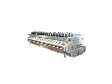 Moulds for Plastic Pipe and Sheet
-
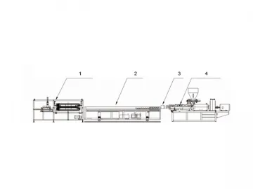
 PVC Window Sill Profile Extrusion Line
-
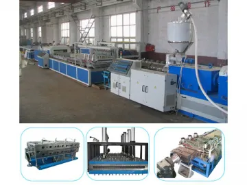
 PVC Profile and PVC/PP/PE Wood Plastic Composite Profile Production Line
-
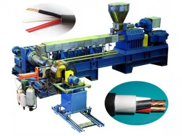 PVC Cable and Wire Production Line
-
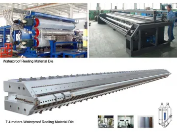 PP, PE Wide Waterproof Geotextile (Geomembrane) Production Line
-
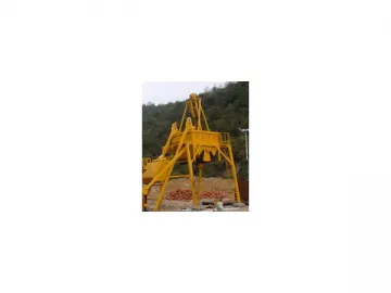
 YLB Series Mobile Asphalt Mixing Plant
-
 Ladies Casual Shirts
-
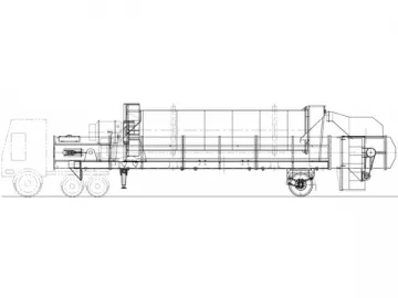
 QLBY Series Mobile Asphalt Mixing Plant
-
 Men's and Women's Pants
-
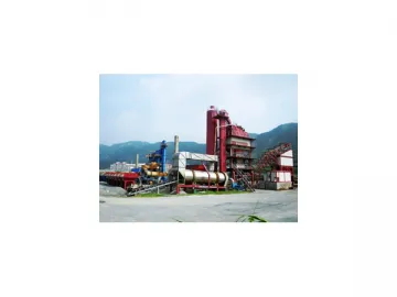 Stationary Asphalt Mixing Plant
-
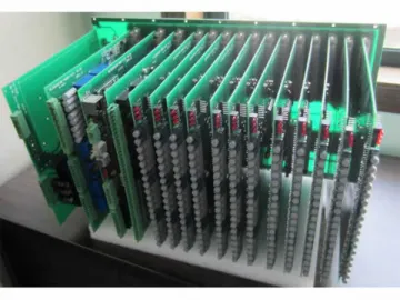 STATCOM Structure