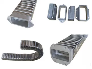
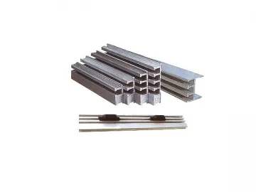
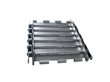
Steel Drag Chain (Drag Chain with Steel Plate and Aluminum Alloy Chain Link)
Among all the drag chains we made, this TL series steel drag chain is a premium cable carrier consists of such main parts as chainplate(made of chrome-plated steel plate), support plate(aluminum alloy), hinge pin(alloy steel) and etc. It could stop the relative motion between cable/rubber tube and chains and avoid deformation.
Features of Steel Drag Chain
1. As the chainplate is plated with chrome coatings, this steel cable carrier has a novel scientific design and is highly flexible in operation, easy in installation and uninstallation;
2. Since the drag chain is made of high-strength abrasion-resistant materials and equipped with premium parts like hinge pin made of alloy cooper, it is highly resistant to abrasion, more flexible to bend, durable in use and hard to be deformed.
Technical Data of Steel Drag Chain
| Model Parameters | TL45 | TL65 | TL95 | TL125 | TL180 | TL225 |
| Chain Pitch(t) | 45 | 65 | 95 | 125 | 180 | 225 |
| Bending Radius(R) | 50 | 75 90 115 125 145 185 | 115 145 200 250 300 | 200 250 300 350 470 500 575 700 750 | 250 300 350 450 490 600 650 | 350 400 600 750 |
| Minimum Width( B mix ) | 30 | 70 | 120 | 120 | 200 | 250 |
| Max Width(B max) | 250 | 350 | 450 | 550 | 650 | 100 |
| Length(L) | Customized | |||||
| Max Diameter of the Support Plate (D1) | 20 | 30 | 50 | 75 | 110 | 150 |
| Max Diameter of Rectangular Hole (D max) | 16 | 26 | 46 | 72 | - | - |
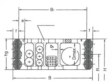
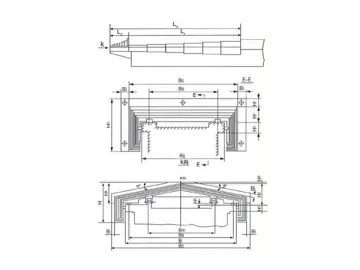
Structure
| 1. servo type connector 2. fixed conncotor 3. bearing surfce 4. preload5. tray | 6. standard connector 7. servo type connector 8. width of support plate9. standard connector | 10. fixed connector 11. width of chain drag 12. connection mode A 13. connection mode B |
Support Plate (Customized Specifications)
Model Ⅰ(Integral type)
Model Ⅱ(Split Type) Model Ⅲ(Framed Type)
Technical Data of Support Plate
| Model | TL45 | TL65 | TL98 | TL125 | TL180 | TL225 | ||||||
| Type | Ⅰ | I | II | Ⅲ | I | II | Ill | I | II | Ill | II | II |
| e | 8 | 10 | 12 | 12 | 15 | 22 | ||||||
| f | 8 | 8 | 10 | 12 | 15 | 15 | ||||||
| b1 | - | - | 3 | - | 4 | - | 5 | - | - | |||
| a1 ~ an D l ~ D n | Customized | |||||||||||
Technical Data of Connectors
| Model | hg | D | C (minimum) | j | k | m | I | I1 | I2 | I3 | I4 | d | h | s |
| TL45 | 30 | 14 | 4 | 9.5 | 13.5 | 11.5 | 60 | 50 | 30 | 3 | 10 | 6.5 | 15 | 2 |
| TL65 | 44 | 26 | 4 | 13 | 17 | 14 | 95 | 75 | 45 | 5 | 15 | 7 | 22 | 3 |
| TL95 | 70 | 46 | 5 | 25 | 30 | 26 | 125 | 105 | 65 | 10 | 20 | 9 | 35 | 4 |
| TL125 | 96 | 72 | 6 | 25 | 30 | 25 | 155 | 130 | 80 | 10 | 25 | 11 | 48 | 5 |
| TL180 | 144 | - | 7 | 25 | 35 | 29 | 210 | 175 | 115 | 10 | 30 | 13 | 72 | 6 |
| TL225 | 200 | - | 10 | 35 | 45 | 39 | 300 | 200 | 140 | 10 | 30 | 18 | 100 | 8 |
Selection
1. D1(diameter of inner cavity hole)=d ≈0.1d, d=outer diameter of wire/cable/ liquid or gas pipe;
2. The height of the energy chain(hg) and its model(TLXX) are determined by the maximum diameter of the of the inner cavity hole(Dmax) of the support plate;
3. The support plate type and the bending diameter are set depending on the application the drag chain;
(1) If used for heavy-duty task(such as carrying large pipes or heavy cables), a drag chain need be equipped with the high strength I type support plate(integral type);
(2) In case that the dimension of the pipe/cable joint is larger than the support plate inner hole’s diameter or the pipe is subject to frequent dismount, the II type support plate(split type) is preferable;
(3) If used for multiple types of pipes/cables, the cable chain could be equipped with III type support plate(frame type);
4. The width of support plate B1 is determined by the quantity of pipes/cables, helping figure out the width of drag chain B;
5. For applications in which support plate with steel belt is a necessity, please inform us of your requirement specially;
6. Additional Chainplates: as the length of support plate is limited, a wide drag chain could be equipped with an additional or more chain boards. A narrow chain will be more stable if equipped with one morechainplate. Meanwhile, a third chain board could separate the pipe casing and the pipe/cable.(note: parameters of TLG: D,23, e and TL: f, j, k.)
7. Elasticity of Hydraulic Tubing: please be noted that the hydraulic tubing will extend or shrink under certain pressures. Therefore, the elasticity of the pipe need be considered especially when the pressure is high and the drag chain is long.
Symbol Meaning
| Length of Drag Chain L | |
| Width of support plate B1 | |
| Bending Diameter | |
| Support Plate Model: I, II, III | |
| Model |
| 1. Support Plate | 2. Support Plate | 3. Elasticity coefficient |
TL II Steel Drag Chain
| 1. Spring Gasket2. Screw Bolts3. Pressing Plate4. Support Plate(outer)5. Servo Connector6. Chainplate | 7. Support Plate(inner)8. Fixed Connector9. Split Support Plate10. Chain Pitch11. Circlip12. Shaft Pin | 13. Outer Chainplate14. Gasket15. Inner Chainplate16. Connector17. Chainplate18. Support Plate | 19. Support Plate20. Pressing Plate21. Outer Chainplate22. Circlip23. Shaft Pin |
TLⅢ Steel-Alluminum Drag Chain
| 1. Chainplate2. Support Plate3. Plastic Spacer | 4. Fixed Connector5. End Bracket6. Fixed Support Bar | 7. Servo Connector8. Plastic Spacer9. Removalbe Support Bar | 10. Chainplate11. Chain Space12. Fixed Connector. |
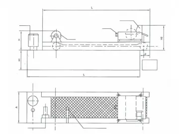
Construcitonal Drawing of Supporting Wheel
| 1. Ordinary(notification is unnecssary when you placing an order)2. Support Roller Bearing 3. Supporting Wheels with no rack4. Supporting Wheels with rack. |

Links:https://www.globefindpro.com/products/71731.html
-
 Coolant Filtration Machine (Paper Bed Filter with Magnetic Separator for Filtration Metals and Non-metals)
-
 Flexible Conduit (Conduit for Cable and Hose Protection)
-
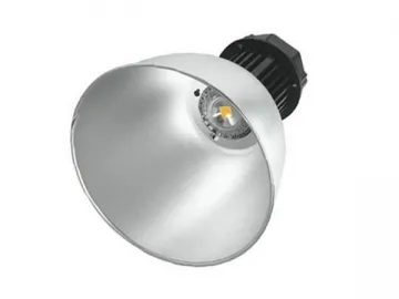
 LED Canopy Light
-
 T Slot Plate (Aluminum Plate Mounting on Machine Tool)
-
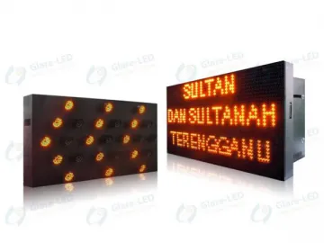 VMS LED Display (Variable Message Sign)
-
 Outdoor LED Display (DIP LED Advertising Display)
-
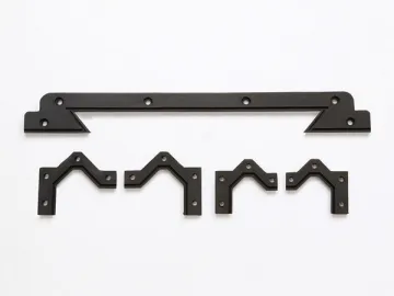 Slideway Wiper (Way Wiper for Machine Tools)
-
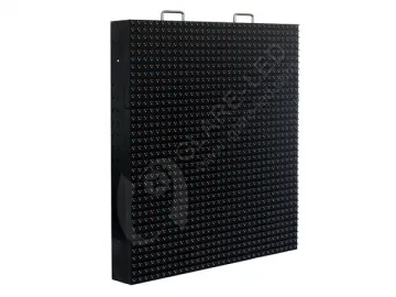
 Outdoor LED Display (SMD LED Video Display)
-
 Chip Conveyor Chain
-
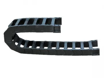 Plastic Drag Chain (Cable Drag Chain made of Reinforced Nylon)
-
 Telescopic Cover (Protection for Metal Chips and Coolant)
-
 Mining Lamp (Metal Halide Lamp for Machine Tool and High Bay Lighting)