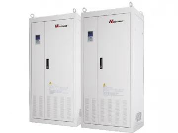
ED3100-FP Series Energy-Saving Variable Frequency Drive for Fan and Pump
It is common practice to allow for some deviations from the rated capacity in design of industrial fans and pumps. Designers also add dampers or valves to regulate the flow of air or liquid into and out of the fan or pumping system. These flow control methods are simple but also wasteful. As a matter of fact, the significant usefulness of our variable frequency drive comes from the large amount of energy it saves in the pump or fan speed control system, eliminating the need for any dampers or valves.
Features of Variable Frequency Drive
1. Overload capacity: rated current×120%/min, rated current ×150%/sec
2. Smooth startup protects the fan and pump from shock load.
3. The PLC system, coupled with the bypass control, ensures the variable frequency drive can freely switch between two fixed frequencies.
4. The speed tracking control allows the drive to deliver a motor speed the same as the previous one. In this way the decelerated motor can retain its speed without experiencing shock load.
5. Automatic energy-saving features adjust the motor speed according to the varying electric loads.
6. Built-in PID functions offer both open loop and closed loop controls.
7. Various other control and protection features are available.
Applications of VFD
Our variable frequency drive can be connected to the fan in an industrial or residential boiler, mine ventilation system, cement or ceramic furnace, dust collection system, the metro station, large workshop, sports venue, and the air compressor.
The variable frequency drive also can be attached to the pump of the urban heating supply system, central air conditioning system, cooling water system, water plant, sewage treatment factory, dyeing equipment, and water supply system
VFD Installation Size
| ED3100P Series specification lis | ||||||||
| Series | kw | H(mm) | W(mm) | D(mm) | H1(mm) | W1(mm) | R(mm) | Note |
| power | Shell Size | Installation Size | Aperture | |||||
| ED3100P | 5.5-7.5 | 270 | 226 | 179 | 256.5 | 210 | 3.25 | Plastic Shell |
| 11-18.5 | 350 | 247 | 232 | 334 | 186 | 4.5 | Metal Shell | |
| 22-30 | 530 | 341 | 285 | 510 | 200 | 5.5 | ||
| 37-45 | 600 | 368 | 281 | 580 | 230 | 5 | ||
| 55-75 | 679 | 394 | 302 | 659 | 300 | 6 | ||
| 93-132 | 825 | 533 | 368.6 | 797 | 420 | 6 | ||
| 160-200 | 1250 | 684 | 470 | 1222 | 420 | 6 | ||
| 160-200 | 1425 | 420 | 470 | 1411 | 420 | |||
| 220-280 | 1500 | 700 | 471 | cabinet Installation | ||||
| 315-400 | 1600 | 830 | 482 | cabinet Installation | ||||
Specifications
| ED3100-FP Series Variable Frequency Drive for Fan and Pump | Specs | |
| Input | Rated voltage and frequency | Single-phase 220V, three-phase 220V, Three-phase 380V; 50Hz/60Hz |
| Allowable variations (tolerance) | Voltage: -20% 20 Voltage unbalance: <3% Frequency: ±5 | |
| Output | Rated voltage | 0~200V /0380V |
| Frequency range | 0Hz~400Hz | |
| Overload capability | 150% for 1 min, 180% for 1s, 200% instant protection required | |
| Main control function | Control mode | PWM modulator (using voltage vector for effective control)Sensorless vector control (SVC) |
| Frequency accuracy | Digital mode: Max frequency ×±0. 01% Analog mode: Max frequency ×±0. 2% | |
| Frequency resolution | Digital mode: 0.01Hz Analog mode: Max frequency ×0.1% | |
| Torque rise | Auto torque riseManual torque rise 1%~30.0% | |
| V/F curve | Linear V/F curveQuadratic V/F curveUser-defined V/F curve | |
| S-curve acceleration/deceleration | Optional time units: Min/sMaximum acceleration and deceleration time: 6000s (adjustable within the range of 0.1~3600s). | |
| DC braking unit | Operating frequency: 0~20HzOperating voltage level: 0~20%Operating time: ± 0~20s | |
| Jog switch | Jog frequency range: 0.1Hz~50.00HzJog acceleration and deceleration time: 0.1~3600s. | |
| Built-in PID | A closed loop control system is formed with the aid of built-in PID which is applicable for process control such as the adjustment of flow rate and water pressure. | |
| Multiple preset speeds | Built-in PLC system, together with control terminals, produces a number of preset speeds. | |
| Weave and wobble | Adjustable wobble frequency | |
| Auto voltage adjustment | When the mains voltage changes, the output voltage is kept constant by adjusting PWM output (AVR function). | |
| Power saving mode | V/F curve is adjustable to varying load conditions so as to maintain an optimal level of energy efficiency all the time. | |
| Auto current control | Current-limiting features prevent the VFD control tripping on a fault caused by excess current. | |
| Sensorless vector control | Torque | 150% torque output at 1Hz Torque adjustment accuracy: 0.1% |
| Automatic display of motor parameters | Check parameters on the display when the motor completely stops in order to achieve optimal control | |
| Run Enable | Command channels for variable frequency drive | Selection of operation modes Setting of control terminals Setting of serial ports |
Links:https://www.globefindpro.com/products/75479.html
