Matrix Switcher Splitter
3G SDI 8×8 Matrix with Reclock
Model: SSW0808R
1. The matrix switcher splitter is a kind of 3G SDI matrix with Reclock function. It supports the arbitrary switching between 8-channel SDI input source and 8-channel SDI output source.
2. The Reclock function means that our product can realize infinite cascade function under ideal conditions. It allows users to connect one or multiple equipment to an output terminal, if one device fails to meet requirements.
3. 3G means that the bandwidth of the audio switching splitter reaches up to 1080P/60HZ. The bandwidth of SDI products which do not support 3G will not reach 1080P/60HZ. Delay may occur in the audio and video transmission process, which will affect a high-definition effect.
4. In addition, the matrix switcher splitter offers the function of over-voltage protection and reverse polarity protection. In this way, the equipment will not be damaged, even if a user plugs in the wrong power supply.
5. Once powered on, the matrix switcher splitter will allow memory to be automatically recovered. Also, this kind of audio and video accessory is specially designed with equalizer IC in its inputs and drive IC in its output. All of the inputs and output are in favor of long coaxial cable.
Specifications
| Support line length (Cable is RG 6) | |
| 3G (1080P 60HZ) Mode | Front up to 100m, followed up by 100m |
| HD (720P 60HZ) Mode | Front up to 220m, followed up by 200m |
| SD (480i) Mode | Front up to 320m, followed up by 300m |
6. For the convenience of user control, the matrix switcher splitter is configured with three switching methods including the panel button, infrared remote control, and RS232. Each output on the panel has an independent button, and it supports IR function. RS232 is mainly applied in projects. Our users can download hyper terminal. The control of equipment can be realized by computer systems. Control instruction is listed as follows.
Shared Control Instruction| QS | Select the connection relationship between the source and sink |
| PON | Turn on the main power supply |
| POFF | Turn off the main power supply |
| Select the input source : serial number of the output channel serial number of the input channel Enter | |
| A1 | A Channel selects Input1 |
| … | … |
| A8 | A Channel selects Input8 |
| … | … |
| H1 | H Channel selects Input1 |
| … | |
| H8 | H Channel selects Input8 |
| Close the output : OFF serial number of the output channel Enter | |
| OFFA | Cut off the signal which was sent to output A, make output A not displayed |
| … | … |
| OFFH | Cut the signal which was sent to output H, make output H not displayed |
| Open the output : ON serial number of the output channel Enter | |
| ONA | Open the signal which was sent to output A, let output A display |
| … | … |
| ONH | Open the signal which was sent to output H, let output H display |
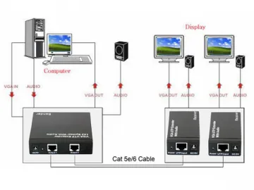
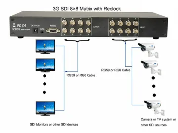
Connection Diagram
Links:https://www.globefindpro.com/products/78815.html
