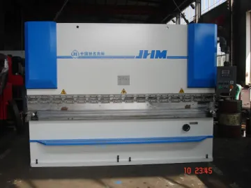
Electro-Hydraulic Press Brake
The electro-hydraulic press brake is designed for sheet metal bending, with various color options to choose from. The main machine is of all steel welded construction and has been through vibration treatment to relieve stress. Driven by a hydraulic system, this sheet metal bender uses imported OMG hydraulic valves providing, stable performance and long service life. Lead time for bulk order is usually 30 days. A certain number of finished products are kept in stock, so as to meet the requirements of rush orders.
Features of Electro-Hydraulic Press Brake
1. The frame of the press brake has been machined in one pass by the CNC floor-standing boring and milling machine, which guarantees parallelism and perpendicularity of every fitting surface.
2. Mounted on the baseplates at both sides of the machine, the oil cylinders drive the slide (or ram) to move up and down.
3. The back gauge distance and ram stroke are displayed on the screen, and can be controlled intelligently. A special device may be used to finely adjust the distance and stroke.
4. During the ram stroke, the operator is able to control its initial synchronization through a torque shaft. The final position of the ram is determined by the bearing block of the ball screw installed within the cylinder. Hence, the press brake performs superbly in synchronization precision and resistance to eccentric load.
5. To adjust the downward stroke, the ordinary motor may drive the ball screw shaft within the cylinder to rotate, enabling the bearing block to move up and down along the shaft. In this way, the press brake realizes causal bending. The E10 electronic counter on the right side of the machine is applied to display the actual stroke of the ram (slide). The ram stroke is adjusted by the bearing block, so as to control the return stroke of the block, improving production efficiency.
6. Its upper die adjustment device is used for compensating the deformation of slide (or ram) and workbench in operation. The operator ought to adjust this device in line with different working conditions, so as to make sure the deformation curves of block and workbench are close to each other, which increases bending precision.
7. With the help of the electro hydraulic control system, the sliding blocks are able to decrease rapidly or slowly, return quickly, move up or down through jog, or stop halfway. The press brake can be operated by hands or through the pedal.
8. The cylinders adopt high-quality VALQUA sealing elements. The hydraulic pipeline is composed of the phosphate-coated tubes and plumbing ferrules, which helps to minimize hydraulic oil pollution.
9. This sheet metal forming machine is equipped with an electrical cabinet power switch and a mechanical interlocking device. Once the door of the cabinet is opened, the machine will automatically power off, ensuring personnel security during operation and maintenance.
10. The press brake is available with different CNC system in accordance with your needs.
Press Brake CNC System
Technical Parameters
| V | 4 | 6 | 8 | 10 | 12 | 14 | 16 | 18 | 20 | 24 | 28 | 32 | 36 | 40 | 45 | 50 | 55 | 60 | 65 | 70 | 80 | 90 | 100 | 120 | |
| B | 2.8 | 4 | 5.5 | 7 | 8.5 | 10 | 11 | 12.5 | 14 | 17 | 20 | 22 | 25 | 28 | 31 | 35 | 38 | 42 | 46 | 49 | 56 | 63 | 70 | 85 | |
| 0.7 | 1 | 1.3 | 1.6 | 2 | 2.3 | 2.6 | 3 | 3.3 | 3.8 | 4.5 | 5 | 6 | 6.5 | 7 | 8 | 9 | 10 | 10.5 | 11 | 13 | 14 | 16 | 19 | ||
| S | 0.5 | 40 | 30 | ||||||||||||||||||||||
| 0.6 | 60 | 40 | 30 | 30 | This table is calculated in line with the tensile strength of plate. σb: 450N/mm Length: 1m When different kinds of plate with diverse length is bent, the force can be obtained according to the proportion. | ||||||||||||||||||||
| 0.8 | 70 | 50 | 40 | 30 | |||||||||||||||||||||
| 1 | 110 | 80 | 70 | 60 | |||||||||||||||||||||
| 1.2 | 120 | 100 | 80 | 70 | 60 | ||||||||||||||||||||
| 1.5 | 150 | 120 | 110 | 90 | 80 | ||||||||||||||||||||
| 2 | 220 | 190 | 170 | 150 | 130 | 110 | |||||||||||||||||||
| 2.5 | 250 | 220 | 200 | 170 | 150 | 130 | |||||||||||||||||||
| 3 | 330 | 290 | 250 | 210 | 180 | 160 | |||||||||||||||||||
| 3.5 | 400 | 330 | 290 | 250 | 220 | 200 | |||||||||||||||||||
| 4 | 440 | 370 | 330 | 290 | 260 | 230 | 210 | ||||||||||||||||||
| 4.5 | 470 | 410 | 370 | 330 | 300 | 270 | 240 | ||||||||||||||||||
| 5 | 510 | 450 | 400 | 360 | 330 | 300 | 270 | 250 | |||||||||||||||||
| 6 | 520 | 470 | 430 | 390 | 360 | 340 | 300 | ||||||||||||||||||
| 8 | 700 | 640 | 600 | 520 | 460 | 420 | |||||||||||||||||||
| 10 | 810 | 720 | 650 | ||||||||||||||||||||||
| 12 | 950 | 780 | |||||||||||||||||||||||
| 14 | 1300 | 1100 | |||||||||||||||||||||||
Note: If there is no special requirement for the angle “R”, the groove width “V” should be 8-10 times of plate thickness "S".
| Specification and model | Normal force | Operating platform length | Distance between columns | Slide block stroke | Throat depth | Main motor power |
| WC67Y-40/2000 | 400 | 2000 | 1590 | 100 | 200 | 5.5 |
| WC67Y-40/2200 | 400 | 2200 | 1590 | 100 | 200 | 5.5 |
| WC67Y-40/2500 | 400 | 2500 | 2090 | 100 | 200 | 5.5 |
| WC67Y-50/2500 | 500 | 2500 | 1900 | 120 | 250 | 5.5 |
| WC67Y-50/3200 | 500 | 3200 | 2600 | 120 | 250 | 5.5 |
| WC67Y-63/2500 | 630 | 2500 | 2050 | 100 | 250 | 5.5 |
| WC67Y-63/3200 | 630 | 3200 | 2600 | 100 | 250 | 5.5 |
| WC67Y-80/3200 | 800 | 3200 | 2600 | 100 | 250 | 7.5 |
| WC67Y-80/4000 | 800 | 4000 | 3200 | 100 | 250 | 7.5 |
| WC67Y-100/2500 | 1000 | 2500 | 1900 | 120 | 320 | 7.5 |
| WC67Y-100/3200 | 1000 | 3200 | 2600 | 120 | 320 | 7.5 |
| WC67Y-100/4000 | 1000 | 4000 | 3200 | 120 | 320 | 7.5 |
| WC67Y-100/5000 | 1000 | 5000 | 4000 | 120 | 320 | 7.5 |
| WC67Y-125/2500 | 1250 | 2500 | 2050 | 130 | 320 | 7.5 |
| WC67Y-125/3200 | 1250 | 3200 | 2600 | 130 | 320 | 7.5 |
| WC67Y-125/4000 | 1250 | 4000 | 3200 | 130 | 320 | 7.5 |
| WC67Y-125/5000 | 1250 | 5000 | 4000 | 120 | 320 | 7.5 |
| WC67Y-160/3200 | 1600 | 3200 | 2600 | 200 | 320 | 11 |
| WC67Y-160/4000 | 1600 | 4000 | 3200 | 200 | 320 | 11 |
| WC67Y-160/5000 | 1600 | 5000 | 4000 | 200 | 320 | 15 |
| WC67Y-160/6000 | 1600 | 6000 | 4800 | 200 | 320 | 15 |
| WC67Y-200/3200 | 2000 | 3200 | 2600 | 200 | 320 | 15 |
| WC67Y-200/4000 | 2000 | 4000 | 3200 | 200 | 320 | 15 |
| WC67Y-200/5000 | 2000 | 5000 | 4000 | 200 | 320 | 15 |
| WC67Y-200/6000 | 2000 | 6000 | 4800 | 200 | 320 | 15 |
| WC67Y-250/3200 | 2500 | 3200 | 2600 | 250 | 400 | 18.5 |
| WC67Y-250/4000 | 2500 | 4000 | 3200 | 250 | 400 | 18.5 |
| WC67Y-250/5000 | 2500 | 5000 | 4000 | 250 | 400 | 18.5 |
| WC67Y-250/6000 | 2500 | 6000 | 4800 | 250 | 400 | 18.5 |
| WC67Y-300/3200 | 3000 | 3200 | 2600 | 250 | 400 | 22 |
| WC67Y-300/4000 | 3000 | 4000 | 3200 | 250 | 400 | 22 |
| WC67Y-300/5000 | 3000 | 5000 | 4000 | 250 | 400 | 22 |
| WC67Y-300/6000 | 3000 | 6000 | 4800 | 250 | 400 | 22 |
| WC67Y-400/4000 | 4000 | 4000 | 3200 | 320 | 400 | 22 |
| WC67Y-400/5000 | 4000 | 5000 | 4000 | 320 | 400 | 22 |
| WC67Y-400/6000 | 4000 | 6000 | 4800 | 320 | 400 | 22 |
| WC67Y-500/6000 | 5000 | 6000 | 4800 | 320 | 400 | 37 |
| WC67Y-600/7000 | 6000 | 7000 | 5600 | 320 | 400 | 45 |
| WC67Y-700/7000 | 7000 | 7000 | 5600 | 320 | 400 | 45 |
| WC67Y-800/6000 | 8000 | 6000 | 4800 | 400 | 500 | 55 |
| WC67Y-1000/6000 | 10000 | 6000 | 4600 | 500 | 600 | 75 |
Links:https://www.globefindpro.com/products/79167.html
-
 CNC Grooving Machine
-
 Roller Leveler
-
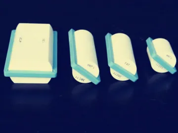 Cercon System Compatible Zirconia Block
-
 Super Translucency Coloring liquid for Zirconia Block
-
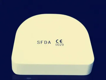 Shutze System Compatible Zirconia Block
-
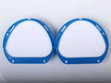 Amann Girrbach CAD/CAM System Compatible Zirconia Block
-
 VMK-0088 Key Cutting Machine
-
 MEII-4840 Mold Engraving Machine
-
 MEII-4242SQ Mold Engraving Machine
-
 MEII-4242 Mold Engraving Machine
-
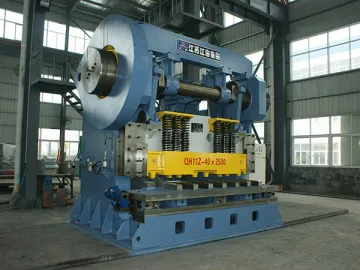 Heavy Duty Mechanical Shear
-
 SE3230 Mold Engraving Machine
