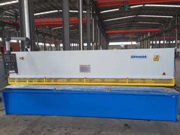
CNC Swing Beam Shear
The CNC hydraulic swing beam shear is provided with 21 models. It is capable of shearing sheet metal with the thickness of 4-12mm and width of 2000-5000mm. An ammonia gas cylinder is employed as the return cylinder, which ensures stable operation. The distance between the bottom blade and upper die can be easily adjusted by a hand lever, allowing step-less blade gap adjustment. Its finger guard is electrically controlled for security and protection. Composed of the CNC control panel and position encoder, the closed-loop control system works rapidly and steadily, and is able to ensure the accuracy of back gauge displacement. In addition, the CNC control panel can fulfill precision compensation, automatic detection and other functions.
Main Machine Construction
1. Frame
The frame of swing beam shear features a rigid structure, providing high durability and good ruggedness. There are two cylinders fixed to the left and right columns. A movable tool rest is placed on the workbench, allowing fine tuning of the lower blade. In addition, ball transfer table is used for convenient material feeding.
2. Top Tool Rest
The tool rest features a welded steel structure. Its downward and upward stroke is powered by the return cylinder as well as said cylinders on the left and right column. It takes the eccentric locking collar as a pivot and swings back and forth, so as to shear materials. Its vertical blade bearing surface has been processed into an arc curve, guaranteeing consistency of the gap between the upper and lower blade.
3. Hold-down
The hold-down is a clamp for holding a sheet metal being sheared, preventing distortion and movement. The hold-down pressure is generated by cylinders on the bearing plate of swing beam shear. Once oil flows into the pressure cylinder, the hold-down feet will overcome the tension from a tension spring to press materials. With the aid of the spring, the device can returns to its original position at the end of shearing. The pressure grows with increasing thickness of materials.
4. Front and Back Gauge
1) Placed on the workbench, the front gauge shows numerical values by means of a scale. The desired gauge distance can be achieved through the adjustment of a stop dog. A long gauge is ideal for machining sheet steel.
2) The back gauge of swing beam shear is mounted on the top tool rest. It swings up and down along with the tool rest. The operator can make an adjustment through a motor. After a gear slows down, the gauge is driven by lead screws and may be adjusted via “ ” or “-” button. Additionally, the operator is able to rotate the regulating wheel for fine adjustment of the back gauge.
5. There are various CNC control panel options to satisfy your demands.
CNC Control Panel for Metal Shear
Technical Parameters
| Model | Allowable Sheet Thickness (mm) | Allowable Sheet Width (mm) | Rake Angle (° ) | Frequency of stroke (times/min) | Back gauge range (mm ) | Main motor power (kw) |
| QC12K-4×2000 | 4 | 2000 | 1° 30 ' | 20 | 20 ~600 | 4 |
| QC12K-4×2500 | 4 | 2500 | 1° 30 ' | 20 | 20 ~600 | 4 |
| QC12K-4×3200 | 4 | 3200 | 1° 30 ' | 18 | 20 ~600 | 5.5 |
| QC12K-4×4000 | 4 | 4000 | 1° 30 ' | 16 | 20 ~600 | 5.5 |
| QC12K-4×5000 | 4 | 5000 | 1° 30 ' | 14 | 20 ~600 | 7.5 |
| QC12K-6×2000 | 6 | 2000 | 1° 30 ' | 20 | 20 ~600 | 7.5 |
| QC12K-6×2500 | 6 | 2500 | 1° 30 ' | 18 | 20 ~600 | 7.5 |
| QC12K-6×3200 | 6 | 3200 | 1° 30 ' | 14 | 20 ~600 | 7.5 |
| QC12K-6×4000 | 6 | 4000 | 1° 30 ' | 14 | 20 ~600 | 7.5 |
| QC12K-6×5000 | 6 | 5000 | 1° 30 ' | 8 | 20 ~600 | 11 |
| QC12K-6×6000 | 6 | 6000 | 1° 30 ' | 10 | 20 ~600 | 11 |
| QC12K-8×2500 | 8 | 2500 | 1° 30 ' | 12 | 20 ~600 | 11 |
| QC12K-8×3200 | 8 | 3200 | 1° 30 ' | 10 | 20 ~600 | 11 |
| QC12K-8×4000 | 8 | 4000 | 1° 30 ' | 8 | 20 ~600 | 11 |
| QC12K-8×6000 | 8 | 6000 | 1° 30 ' | 10 | 20 ~600 | 22 |
| QC12K-10×2500 | 10 | 2500 | 1° 30 ' | 10 | 20 ~600 | 15 |
| QC12K-10×3200 | 10 | 3200 | 1° 30 ' | 10 | 20 ~600 | 15 |
| QC12K-12×2500 | 12 | 2500 | 1° 30 ' | 8 | 20 ~800 | 18.5 |
| QC12K-12×3200 | 12 | 3200 | 1° 30 ' | 10 | 20 ~800 | 18.5 |
| QC12K-12×4000 | 12 | 4000 | 1° 30 ' | 10 | 20 ~800 | 18.5 |
| QC12K-12×5000 | 12 | 5000 | 1° 30 ' | 8 | 20 ~800 | 22 |
window.onload =function(){setItemByDivId('container','one|two|three|four|five|six|seven|eight','etw_link','color:#fff; background:#1d4ca6;','color:#fff;background:#4a4a4a','setclass');doget('/loadByJs.php?type=loadByReg&page=/2-5-cnc-control-panel/158928&start=start&end=end','setresult')}
Links:https://www.globefindpro.com/products/79199.html
-
 Mechanical Three-Roll Machine
-
 General Purpose Sintered Diamond Blade
-
 PTFE Adhesive Tape
-
 PTFE Coated Kevlar
-
 Sintered Diamond Blade for Stone
-
 Brazed Diamond Wire Saw
-
 CM-Smart 5 Dental Milling Machine
-
 ST Pre-coloured Dental Zirconia Block
-
 Zirconia Sintering Furnace
-
 Hydraulic Rolling Shear
-
 Dental Full Zirconia Crown
-
 Sircona in Lab System Compatible Zirconia Block
