CNC Pipe Bender
Features
1. The electronic control system of our CNC pipe bender is imported from renowned brand of Japan. The ultra-large Mitsubishi PLC system is capable of compiling 1000 sets of files.
2. The Windows operating system is built in the industrial computer and cooperates with the servo system of Mitsubishi.
3. This product enables automatic error and failure detections which will be displayed on the screen so that the operator can easily remove obstacles.
4. In addition to PLC system, hydraulic drive, human-machine touch screen and English display, this CNC pipe bender also can complete the prefabrication of tubes with various turning angles. Meanwhile, it is available with manual, semi-automatic and automatic operating modes.
5. Except the function of starting up, the foot switch also enables emergency stop.
6. Thanks to the advanced, imported and reliable hydraulic, control, drive and display systems, this machine features high accuracy and efficiency, suitable for mass production and meeting up with advanced international and domestic levels.
7. It is designed with complete devices for bending 3D tubes and all the procedures will be automatically finished after the input of program. It has become a necessary product for tube bending with the advantages of easy operation, stable performance, high efficiency and safety coefficient.
8. Apart from the following models, we also provide the CNC pipe bender in other models to process the tubes with diameters of 25mm, 50mm, 75mm, 100mm, 130mm and 189mm. Customization is available upon your specific drawing.
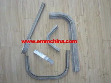
Technical Parameters
2A: 2 axis servo
A: Servo motor
3A: 3 axis servo
S: Die (bending radius)
Technical Parameters
| Item | Unit | EM183A-1S | 1.EM382A-1S 1.EM383A-1S | 1.EM632A-1S 2.EM633A-1S | 1. EM892A-1S 2.EM893A-1S | EM1152A-1S | EM1682A-1S | EM2192A-1S | |
| Maximum bending tube diameter × wall thickness | mm | Φ18×1.6 | Φ38×2 | Φ63×4 | Φ89×8 | Φ115×10 | Φ168×14 | Φ219×23 | |
| Maximum bending radius (1) | mm | R80 | R180 | R250 | R250 | R350 | R500 | R700 | |
| Minimum bending radius (2) | mm | Upon tube diameter | Upon tube diameter | Upon tube diameter | Upon tube diameter | Upon tube diameter | Upon tube diameter | Upon tube diameter | |
| Maximum bending angle | degree | 195 | 190 | 190 | 190 | 190 | 190 | 190 | |
| Maximum feed length (3) | mm | 1500 | 2500 | 3000 | 3000 | 3000 | 3600 | 4500 | |
| Feed mode | Direct, clamping | ||||||||
| Working speed | Tube bending speed | Max. 200゚/s | Max. 150゚/s | Max. 85゚/s | Max. 30゚/s | Max. 30゚/s | Max. 25゚/s | Max. 20゚/s | |
| Tube turning speed | Max. 200゚/s | Max. 200゚/s | Max. 200゚/s | Max. 160゚/s | Max. 160゚/s | Max. 160゚/s | Max. 160゚/s | ||
| Feed speed | Max. 1000mm/s | Max. 1000mm/s | Max. 1000mm/s | Max. 800mm/s | Max. 800mm/s | Max. 600mm/s | Max. 600mm/s | ||
| Accuracy | Tube bending accuracy | ±0.1゚ | ±0.1゚ | ±0.1゚ | ±0.1゚ | ±0.15゚ | ±0.15゚ | ±0.15゚ | |
| Tube turning accuracy | ±0.1゚ | ±0.1゚ | ±0.1゚ | ±0.1゚ | ±0.1゚ | ±0.1゚ | ±0.1゚ | ||
| Feed accuracy | ±0.1mm | ±0.1mm | ±0.1mm | ±0.1mm | ±0.1mm | ±0.1mm | ±0.1mm | ||
| Data input mode | 1. Coordinate (X, Y, Z) 2. Working value (Y, B, C) | 1. Coordinate (X, Y, Z) 2. Working value (Y, B, C) | 1. Coordinate (X, Y, Z) 2. Working value (Y, B, C) | 1. Coordinate (X, Y, Z) 2. Working value (Y, B, C) | 1. Coordinate (X, Y, Z) 2. Working value (Y, B, C) | 1. Coordinate (X, Y, Z) 2. Working value (Y, B, C) | 1. Coordinate (X, Y, Z) 2. Working value (Y, B, C) | ||
| Tube bending mode | 1. Servo: 1KW (over 3 axis) | 1. Servo: 5KW (over 3 axis)2. Hydraulic | 1. Servo: 7KW (over 3 axis)2. Hydraulic | 1. Servo: 15KW (over 3 axis)2. Hydraulic | 1. Hydraulic | 1. Hydraulic | 1. Hydraulic | ||
| Servo motor power for tube turning | KW | 0.4 | 0.75 | 0.75 | 1.5 | 2 | 3.5 | 5 | |
| Servo motor power for feeding | KW | 0.75 | 1 | 1.5 | 2 | 3.5 | 5 | 7 | |
| Allowable bent tube number | 16 pieces (PLC system PPC) | ||||||||
| Storable component number (4) | 2 million sets (PLC system PPC) | ||||||||
| Hydraulic motor power | KW | 3 | 4 | 5.5 | 11 | 22 | 22 | 30 | |
| Maximum system pressure (adjustable) | MPa | 10 | 12 | 12 | 14 | 14 | 16 | 16 | |
| Overall dimension | mm | 2760×690×1000 | 3860×720×1230 | 5200×1300×1560 | 5650×1350×1360 | 6120×1460×1400 | 8100×1955×1660 | 8500×2400×1980 | |
| Weight | kg | 800 | 1500 | 3000 | 5500 | 10000 | 20000 | 40000 | |
| Note: (1) and (3) are upon the specific requirements of customers. (2) depends on the tube diameter and (4) can be increased. | |||||||||
| Item | Unit | 1. EM185A-2S 2.EM185A-3S | 1. EM255A-2S 2. EM255A-3S | 1. EM385A-2S 2. EM385A-3S | 1. EM505A-2S 2.EM505A-3S | 1. EM635A-2S 2.EM635A-3S | 1. EM755A-2S 2.EM755A-3S | 1. EM895A-2S 2.EM895A-3S | 1. EM1005A-2S 2. EM1005A-3S | |
| Maximum bending tube diameter × wall thickness | mm | Φ18×2 | Φ25×1.6 | Φ38×2 | Φ50×3 | Φ63×4 | Φ75×4 | Φ89×8 | Φ100×8 | |
| Maximum bending radius (1) | mm | R80 | R100 | R180 | R250 | R250 | R250 | R250 | R350 | |
| Minimum bending radius (2) | mm | Upon tube diameter | Upon tube diameter | Upon tube diameter | Upon tube diameter | Upon tube diameter | Upon tube diameter | Upon tube diameter | Upon tube diameter | |
| Maximum bending angle | degree | 195 | 190 | 190 | 190 | 190 | 190 | 190 | 190 | |
| Maximum feed length (3) | mm | 1500 | 2200 | 2500 | 3000 | 3000 | 3000 | 3000 | 3000 | |
| Feed mode | Direct, clamping | |||||||||
| Working speed | Tube bending speed | Max. 200゚/s | Max. 200゚/s | Max. 150゚/s | Max. 85゚/s | Max. 85゚/s | Max. 40゚/s | Max. 30゚/s | Max. 30゚/s | |
| Tube turning speed | Max. 200゚/s | Max. 200゚/s | Max. 200゚/s | Max. 200゚/s | Max. 200゚/s | Max. 160゚/s | Max. 160゚/s | Max. 160゚/s | ||
| Feed speed | Max. 1000mm/s | Max. 1000mm/s | Max. 1000mm/s | Max. 1000mm/s | Max. 1000mm/s | Max. 800mm/s | Max. 800mm/s | Max. 800mm/s | ||
| Accuracy | Tube bending accuracy | ±0.1゚ | ±0.1゚ | ±0.1゚ | ±0.1゚ | ±0.1゚ | ±0.1゚ | ±0.1゚ | ±0.1゚ | |
| Tube turning accuracy | ±0.1゚ | ±0.1゚ | ±0.1゚ | ±0.1゚ | ±0.1゚ | ±0.1゚ | ±0.1゚ | ±0.1゚ | ||
| Feed accuracy | ±0.1mm | ±0.1mm | ±0.1mm | ±0.1mm | ±0.1mm | ±0.1mm | ±0.1mm | ±0.1mm | ||
| Data input mode | 1. Coordinate (X, Y, Z) 2. Working value (Y, B, C) | 1. Coordinate (X, Y, Z) 2. Working value (Y, B, C)) | 1. Coordinate (X, Y, Z) 2. Working value (Y, B, C) | 1. Coordinate (X, Y, Z) 2. Working value (Y, B, C) | 1. Coordinate (X, Y, Z) 2. Working value (Y, B, C) | 1. Coordinate (X, Y, Z) 2. Working value (Y, B, C) | 1. Coordinate (X, Y, Z) 2. Working value (Y, B, C) | 1. Coordinate (X, Y, Z) 2. Working value (Y, B, C) | ||
| Tube bending mode | 1. Servo: 1KW (over 3 axis) | 1. Servo: 2KW (over 3 axis) | 1. Servo: 5KW (over 3 axis) | 1. Servo: 5KW (over 3 axis) | 1. Servo: 1KW (over 3 axis) | 1. Servo: 2KW (over 3 axis) | 1. Servo: 5KW (over 3 axis) | 1. Servo: 5KW (over 3 axis) | ||
| Servo motor power for tube turning | KW | 0.4 | 0.4 | 0.75 | 0.75 | 0.75 | 1 | 1.5 | 1.5 | |
| Servo motor power for feeding | KW | 0.75 | 0.75 | 1 | 1 | 1 | 1.5 | 2 | 3.5 | |
| Allowable bent tube number | 16 pieces (PLC system PPC) | |||||||||
| Storable component number (4) | 2 million sets (PLC system PPC) | |||||||||
| Hydraulic motor power | KW | 3 | 3 | 4 | 5.5 | 5.5 | 7.5 | 11 | 15 | |
| Maximum system pressure (adjustable) | MPa | 10 | 12 | 12 | 12 | 12 | 12 | 14 | 14 | |
| Bending die diameter difference (5) | mm | Max. 30 | Max. 35 | Max. 50 | Max. 75 | Max. 80 | Max. 90 | Max. 100 | Max. 110 | |
| Overall dimension | mm | 2760×690×1000 | 4060×780×1100 | 4200×850×1550 | 4900×1300×1700 | 5200×1300×1750 | 5200×1350×1230 | 5650×1350×1360 | 5700×1350×1400 | |
| Weight | kg | 800 | 1000 | 1500 | 3500 | 3800 | 4500 | 5500 | 6000 | |
| Note: (1), (3) and (5) are upon the specific requirements of customers. (2) depends on the tube diameter and (4) can be increased. | ||||||||||
Related Names
Steel Conduit Bending Equipment | Square Tubing Bender | CNC Tube Bending Machine
Links:https://www.globefindpro.com/products/81366.html
-
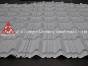 GWC29-193-965 Glazed Roof Tile Roll Forming Machine
-
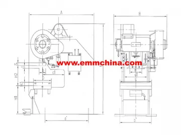 EMS21 Series C-Frame Deep-Throat Fixed Bolster Mechanical Presses
-
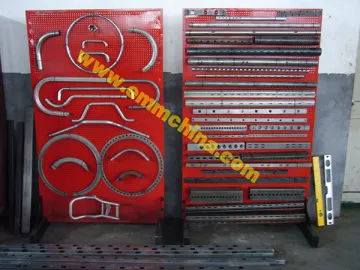 Automatic Pipe Punching Line
-
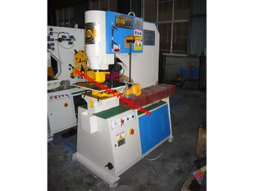 Hydraulic Punching Machine
-
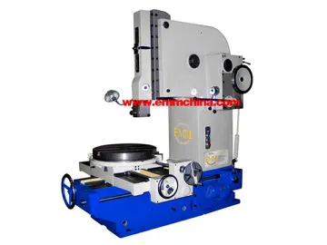 Mechanical Slotting Machine
-
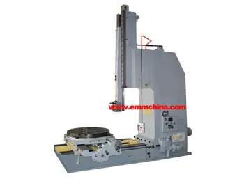 Hydraulic Slotting Machine
-
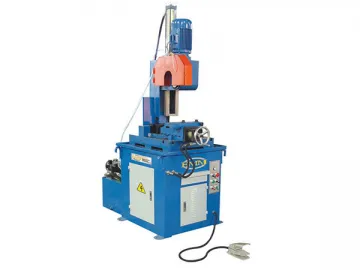 Hydraulic Semi-Automatic Pipe Cutting Circular Saw
-
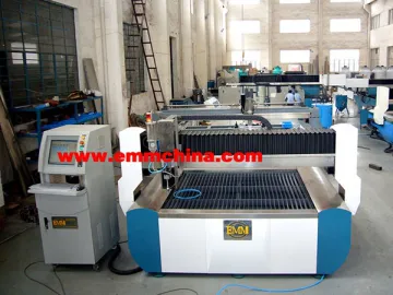 CNC Water Jet Cutter
-
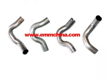 ED Series Double Head Pipe Bender
-
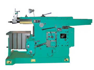 Shaping Machine
-
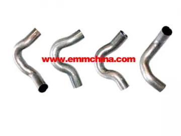 EB Series Single Head 3D Pipe Bender
-
 Manual Surface Grinder
