TL Series Steel Cable Drag Chains
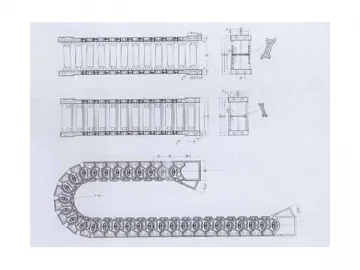
TL series steel cable drag chain is mainly comprised of chrome-plated steel side plates and extruded aluminum crossbars held together by the alloy steel dowel pin. This cable carrier does not allow unwanted relative motion between the chain and cables or rubber hoses. Neither does it deform under stress. Chrome-plated side plate gives a unique exterior. Its reasonable structure is flexible but rigid, allowing assembly ease and reliable operation. High-strength, wear-resistant copper alloy is used for dowel pin making, which enables the side plate to swing more easily with less effort while producing little noise. Such a dowel pin is able to withstand long time of use without sagging.
In addition to its utilitarian purpose, the drag chain also creates a stunning decorative effect on the machine tool it is attached to, thereby making domestic machine tool as well as equipment stand out from global competition.
Specifications
1. Maximum moving speed: 40m/min
2. When the cable carrier is moving at its maximum speed, its sound pressure level is no more than 68db.
3. Able to withstand more than 1million times of use for traversing motion.
Parameters
| TL30 | LT45 | LT65 | LT80 | LT95 | LT115 | LT125 | LT155 | LT180 | LT225 | LT250 | |
| Pitch (t) | 30 | 45 | 65 | 80 | 95 | 115 | 125 | 155 | 180 | 225 | 250 |
| Bending Radius (R) | 40 | 50, 75, 90, 114, 145 | 75, 90, 115, 125, 145, 185 | 100, 115, 125, 145, 185, 200, 250, 300 | 115, 145, 200, 250, 300 | 145, 200, 225, 250, 300, 350 | 200, 250, 300, 350, 470, 500, 575, 700, 750 | 200, 250, 300, 350, 450, 500, 600 | 250, 300, 350, 450, 490, 600, 650 | 400, 450, 600, 750, 800, 850, 1000 | 400, 450, 500, 600, 750, 800, 1000 |
| Drag Chain Minimum Width (Bmini) | 40 | 35 | 50 | 55 | 60 | 70 | 80 | 90 | 100 | 160 | 190 |
| Drag Chain Height (H) | 25 | 32 | 44 | 56 | 70 | 86 | 100 | 120 | 144 | 200 | 220 |
| Drag Chain Length (L) | Tailored to order | ||||||||||
| Max. Hole Diameter in the Cable Separator Plate (D1) | 10 | - | 30 | 35 | 48 | 63 | 68 | 97 | 110 | 146 | 166 |
| Self-Supporting Length | 3 | 4 | 5 | 8 | 9 | 10 | 10 | 10 | 10 | 12 | 14 |
1. This series of drag chain is manufactured by using Italian technology.
2. Custom options for bending radius or special structural design are available upon request.
3. When customer required chain width exceeds the maximum value, the production will be completed by combining together three parallel cable carriers.
Cable Carrier Selection
1. D1=d ≈0.1d(convert the value to an integer). The symbol “d” represents the diameter of electric wires, cables, or hoses.
2. Height of side plates and model of cable carrier are calculated based on the D1 value.
3. Bending radius is determined from the consideration of specific functions of the cable carrier.
I. To accommodate large-diameter, heavyweight cables, I-model is preferred over the other two models.
II. For applications that require frequent disassembly and repair or when the hose is bigger than the hole it needs to pass through, II model can provide you the ideal solution.
III. Dividing a variety of cables or hoses with different specifications is now easier than ever through the III model drag chain.
4. Depending on the number of cables or hoses, the width of internal separator or the chain width is determined.
5. If the use of cable carrier is much limited by the working environment, you can request for elastic steel straps to provide protection for the cable separator plate.
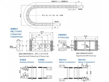
TL 45 Series Installation Drawing
Ordering Examples
TL45III-90×5500: for TL45 series with III-model cable separator, bending radius R=90, and chain length L=5500
TL65 Series Installation Drawing
Ordering Example
TL65III-115×200×6500: for TL65 series with III-model cable separator, bending radius R=115, chain width Bi=200, and chain length=6500.
I-model: one-piece type (Bores are drilled upon your request.)
II-model: It is comprised of the upper and lower parts (Bores are drilled upon your request.)
III-model: This model consists of top and bottom aluminum crossbars with spacers placed between them. (Spacers are tailored to customer-specific requirements.)
TL80 Series Installation Drawing
Ordering Example
TL80III-125×200×6500: for TL80 series with III-model cable separator, bending radius R=125, chain width Bi=200, and chain width L=6500.
I-model: one-piece type (Bores are drilled upon your request.)
II-model: It is comprised of the upper and lower parts (Bores are drilled upon your request.)
III-model: This model consists of top and bottom aluminum crossbars with spacers placed between them. (Spacers are tailored to customer-specific requirements.)
TL95 Series Installation Drawing
Ordering Example
TL95III-250×300×7500: for TL95 series with III-model cable separator, bending radius R=250, chain width Bi=300, and chain width L=7500.
I-model: one-piece type (Bores are drilled upon your request.)
II-model: It is comprised of the upper and lower parts (Bores are drilled upon your request.)
III-model: This model consists of top and bottom aluminum crossbars with spacers placed between them. (Spacers are tailored to customer-specific requirements.)
TL115 Series Installation Drawing
Ordering Example
TL115III-250×300×7500: for TL115 series with III-model cable separator, bending radius R=250, chain width Bi=300, and chain width L=7500.
I-model: one-piece type (Bores are drilled upon your request.)
II-model: It is comprised of the upper and lower parts (Bores are drilled upon your request.)
III-model: This model consists of top and bottom aluminum crossbars with spacers placed between them. (Spacers are tailored to customer-specific requirements.)
TL125 Series Installation Drawing
Ordering Example
TL125III-250×300×7800: for TL115 series with III-model cable separator, bending radius R=250, chain width Bi=300, and chain width L=7800.
I-model: one-piece type (Bores are drilled upon your request.)
II-model: It is comprised of the upper and lower parts (Bores are drilled upon your request.)
III-model: This model consists of top and bottom aluminum crossbars with spacers placed between them. (Spacers are tailored to customer-specific requirements.)
TL155 Series Installation Drawing
Ordering Example
TL155III-250×300×8800: for TL115 series with III-model cable separator, bending radius R=250, chain width Bi=300, and chain width L=8800.
I-model: one-piece type (Bores are drilled upon your request.)
II-model: It is comprised of the upper and lower parts (Bores are drilled upon your request.)
III-model: This model consists of top and bottom aluminum crossbars with spacers placed between them. (Spacers are tailored to customer-specific requirements.)
TL180 Series Installation Drawing
Ordering Example
TL180III-250×300×9800: for TL115 series with III-model cable separator, bending radius R=250, chain width Bi=300, and chain width L=9800.
I-model: one-piece type (Bores are drilled upon your request.)
II-model: It is comprised of the upper and lower parts (Bores are drilled upon your request.)
III-model: This model consists of top and bottom aluminum crossbars with spacers placed between them. (Spacers are tailored to customer-specific requirements.)
TL225 Series Installation Drawing
Ordering Example
TL225III-600×400×12000: for TL115 series with III-model cable separator, bending radius R=600, chain width Bi=400, and chain width L=12000.
I-model: one-piece type (Bores are drilled upon your request.)
II-model: It is comprised of the upper and lower parts (Bores are drilled upon your request.)
III-model: This model consists of top and bottom aluminum crossbars with spacers placed between them. (Spacers are tailored to customer-specific requirements.)
TL250 Series Ordering Example
TL250III-600×400×12000: for TL115 series with III-model cable separator, bending radius R=600, chain width Bi=400, and chain width L=12000.
I-model: one-piece type (Bores are drilled upon your request.)
II-model: It is comprised of the upper and lower parts (Bores are drilled upon your request.)
III-model: This model consists of top and bottom aluminum crossbars with spacers placed between them. (Spacers are tailored to customer-specific requirements.)
Related Names
Wear Resistant Chain | Hollow Pin Chain | Leaf Chains
Links:https://www.globefindpro.com/products/81699.html
-
 Folding Concertina Bellow Slideway Covers
-
 Fixed Machine Leveling Feet
-
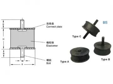 Machine Vibration Damper
-
 Flexible Dust Collection Hose
-
 S78 Series Advanced Anti Vibration Mounts
-
 S79 Series Advanced Anti Vibration Mounts
-
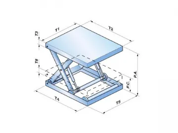 Square Type Machine Shield
-
 Multi Socket
-
 Waterproof Explosion-Proof Steel Braided Hose
-
 Rubber Bellows for Leadscrews
-
 PE Corrugated Hose
-
 Silent Engineering Plastic Cable Drag Chains
