PC Hydraulic Accumulator Charging Kit
Model Explanation
PC-25-3-G0-K0
1 2 3 4 5
1. Model code
2. Pressure gauge range in Mpa: 25 (standard), 10, 40, 60
3. Charging hose length in meter: 3 (standard), 6, 10
4. Connection to gas bottle: G0 means conforming to Chinese National Standards, and can be omitted
5. Storage case: K0 means case suitable for charging unit and repair tools, while K1 indicates case suitable for charging unit only.
General Introduction
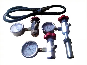
The PC hydraulic accumulator charging kit is applicable for the pressure detection, pressure adjustment and pressurization process for bladder and piston accumulators. During working stage, one end is connected to the gas valve of accumulator, and the other end is connected to nitrogen gas cylinder with the help of a flexible hose.
The pressure gauge is introduced from Germany, and the high pressure hose is responsible for gas delivery from nitrogen cylinder to the accumulator. In addition, this product allows simple operation, and it could be moved to other working sites conveniently.
Structure
This hydraulic accumulator charging kit is made up of several components. For example, the charging head is equipped with pressure gauge and built-in bleed valve, and the flexible hose is usually 3 meters long. On the other hand, the connection adapter is used to connect different gas valves of accumulators, and it contains several types which are 7/8"-14 UNF, 5/8"-18 UNF and 0.305"-32 NFT (8V1). Of course, these components are stored in a case.
Operation Guide
1. Before using this accumulator charging kit to detect, reduce or increase gas pressure, please remove accumulator from the hydraulic line first. Then, dismount the valve protection cap, and attach the charging unit to the accumulator. Please be noted that the pressure gauge should be set at a place that allows easy and clear reading, and the bleed valve will be closed by rotating it clockwise.
2. When detecting gas pressure, please rotate the open/close handle clockwise to open the gas valve, and the reading of the pressure gauge is the present gas pressure. If gas pressure needs to be lowered, please rotate the bleed valve gradually in counterclockwise direction to discharge nitrogen inside the accumulator into the atmosphere.
3. For pressurization process, two ends of the charging hose are connected to charging head and nitrogen cylinder, respectively. Then, turn on the valve of nitrogen bottle slowly to let nitrogen gas flows into accumulator steadily until predetermined gas pressure is achieved. After that, close the valve of nitrogen bottle and wait 5-10 minutes to make sure that the accumulator temperature is the same as ambient temperature before checking whether the gas pressure is of desired value.
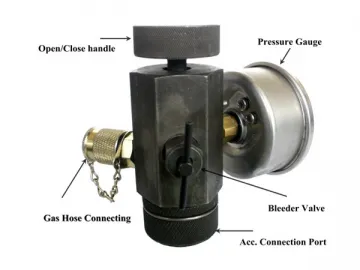
4. When dismounting charging tools, please rotate the open/close handle in counterclockwise direction to close gas valve, and rotate the bleed valve counterclockwise to release the small amount of residual nitrogen inside charging tools to atmosphere. Then, take down the charging tools, and use soap water to detect whether nitrogen leaks. Finally, reinstall the valve protection cap, and fasten it manually.
5. Please strictly follow these operation procedures when using our accumulator charging kit to avoid potential dangers.
Related Names
Nitrogen Filling Unit | Nitrogen Inflator | Hydraulic Accessories
Links:https://www.globefindpro.com/products/82207.html


