Hydraulic Tandem Press Brake
The hydraulic tandem press brake combines two sets of WC67Y series hydraulic press brake together, and an interlock device is also applied. These two metal bending machines can work synchronously to bend ultra long workpieces, and they can also run separately to enhance the utilization rate. The hydraulic tandem press brake has an optional deflection compensation device to improve bending precision.
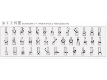
As a sheet metal processing solutions provider, we design this range of hydraulic bending brake into variety of models to suit varied application demands. The detailed specifications are listed below.
Technical Parameters| Model | Nominal force (kN) | Work table length (mm) | Distance between vertical columns (mm) | Throat depth (mm) | Slide stroke (mm) | Max. Open height (mm) | Adjustment range of slide stroke (mm) | Main motor power (kW) | Net weight (kg) | Overall Dimensions (L×W×H, mm) |
| 2-WC67Y-125/3200 | 1250×2 | 3200×2 | 2910 | 320 | 120 | 415 | 100 | 7.5×2 | 8150×2 | 6950×1850×2690 |
| 2-WC67Y-125/4000 | 1250×2 | 4000×2 | 3710 | 320 | 120 | 415 | 100 | 7.5×2 | 9800×2 | 8750×1850×2800 |
| 2-WC67Y-160/3200 | 1600×2 | 3200×2 | 2830 | 320 | 200 | 455 | 160 | 11×2 | 12000×2 | 6950×1940×2630 |
| 2-WC67Y-160/4000 | 1600×2 | 4000×2 | 3630 | 320 | 200 | 455 | 160 | 11×2 | 14000×2 | 8700×1940×2800 |
| 2-WC67Y-160/6000 | 1600×2 | 6000×2 | 5630 | 320 | 200 | 455 | 160 | 11×2 | 19500×2 | 12700×2340×3100 |
| 2-WC67Y-200/3200 | 2000×2 | 3200×2 | 2800 | 320 | 200 | 455 | 160 | 15×2 | 15800×2 | 7100×2000×2970 |
| 2-WC67Y-200/4000 | 2000×2 | 4000×2 | 3600 | 320 | 200 | 455 | 160 | 15×2 | 17200×2 | 8900×2000×2990 |
| 2-WC67Y-200/6000 | 2000×2 | 6000×2 | 5600 | 320 | 200 | 455 | 160 | 15×2 | 24600×2 | 12900×2100×3700 |
| 2-WC67Y-250/3200 | 2500×2 | 3200×2 | 2850 | 400 | 250 | 560 | 200 | 18.5×2 | 19200×2 | 7150×2200×3100 |
| 2-WC67Y-250/4000 | 2500×2 | 4000×2 | 3650 | 400 | 250 | 560 | 200 | 18.5×2 | 21500×2 | 8950×2200×3300 |
| 2-WC67Y-250/6000 | 2500×2 | 6000×2 | 5650 | 400 | 250 | 560 | 200 | 22×2 | 28800×2 | 12950×2300×3700 |
| 2-WC67Y-300/3200 | 3000×2 | 3200×2 | 2720 | 400 | 250 | 560 | 200 | 22×2 | 22800×2 | 7200×2300×3500 |
| 2-WC67Y-300/4000 | 3000×2 | 4000×2 | 3520 | 400 | 250 | 560 | 200 | 22×2 | 24900×2 | 8800×2300×3600 |
| 2-WC67Y-300/6000 | 3000×2 | 6000×2 | 5520 | 400 | 250 | 560 | 200 | 30×2 | 32000×2 | 12800×2600×3800 |
| 2-WC67Y-400/3200 | 4000×2 | 3200×2 | 2800 | 400 | 320 | 630 | 270 | 30×2 | 24000×2 | 7100×2680×3440 |
| 2-WC67Y-400/4000 | 4000×2 | 4000×2 | 3600 | 400 | 320 | 630 | 270 | 30×2 | 30000×2 | 8800×2680×3540 |
Bending Force (Air Bending)
| v | 4 | 6 | 8 | 10 | 12 | 14 | 16 | 18 | 20 | 24 | 28 | 32 | 36 | 40 | 45 | 50 | 55 | 60 | 65 | 70 | 80 | 90 | 100 | 120 | |
| b | 2.8 | 4 | 5.5 | 7 | 8.5 | 10 | 11 | 12.5 | 14 | 17 | 20 | 22 | 25 | 28 | 31 | 35 | 38 | 42 | 46 | 49 | 56 | 63 | 70 | 85 | |
| 0.7 | 1 | 1.3 | 1.6 | 2 | 2.3 | 2.6 | 3 | 3.3 | 3.8 | 4.5 | 5 | 6 | 6.5 | 7 | 8 | 9 | 10 | 10.5 | 11 | 13 | 14 | 16 | 19 | ||
| S | 0,5 | 40 | 30 | This chart is calculated according to these assumptions: the tensile strength of sheetis 450N/mm2, and the length is 1m.Bending force under other condition can be obtained as well depending on the formula below this chart. | |||||||||||||||||||||
| 0.6 | 60 | 40 | 30 | 30 | |||||||||||||||||||||
| 0.8 | 70 | 50 | 40 | 30 | |||||||||||||||||||||
| 1 | 110 | 80 | 70 | 60 | |||||||||||||||||||||
| 1.2 | 120 | 100 | 80 | 70 | 60 | ||||||||||||||||||||
| 1.5 | 150 | 120 | 110 | 90 | 80 | ||||||||||||||||||||
| 2 | 220 | 190 | 170 | 150 | 130 | 110 | |||||||||||||||||||
| 2.5 | 250 | 220 | 200 | 170 | 150 | 130 | |||||||||||||||||||
| 3 | 330 | 290 | 250 | 210 | 180 | 160 | |||||||||||||||||||
| 3.5 | 400 | 330 | 290 | 250 | 220 | 200 | |||||||||||||||||||
| 4 | 440 | 370 | 330 | 290 | 260 | 230 | 210 | ||||||||||||||||||
| 4.5 | 470 | 410 | 370 | 330 | 300 | 270 | 240 | ||||||||||||||||||
| 5 | 510 | 450 | 400 | 360 | 330 | 300 | 270 | 250 | |||||||||||||||||
| 6 | 520 | 470 | 430 | 390 | 360 | 340 | 30-0 | ||||||||||||||||||
| 8 | 700 | 640 | 600 | 520 | 460 | 420 | |||||||||||||||||||
| 10 | 810 | 720 | 650 | ||||||||||||||||||||||
| 12 | 950 | 780 | |||||||||||||||||||||||
| 14 | 1300 | 1100 | |||||||||||||||||||||||
Calculating formula: P=650S2L/V (σb=450N/mm2)
P: Bending force (kN)
S: Sheet thickness (mm)
L: Sheet length (m)
V: Opening of bottom die (mm)
Diagram of Workpiece Processing
Links:https://www.globefindpro.com/products/82927.html
-
 SS100 Material Hoist
-
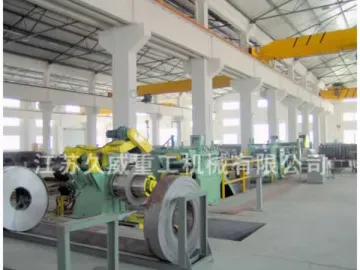 Plate Leveling Machine
-
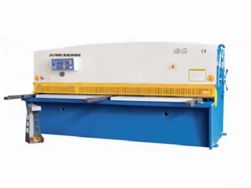 Hydraulic Swing Beam Shear
-
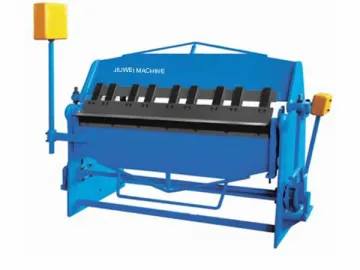 Manual Sheet Metal Folding Machine
-
 Suspended Platform Hoist
-
 Three-Roll Hydraulic Plate Bending Machine
-
 DIN 558
-
 CNC Hydraulic Press Brake
-
 Hex Socket Head Cap Screw
-
 Hydraulic Press Brake
-
 Adjustable 3-Roll Plate Bending Machine
-
 Hex Bolt
