3 Roll Plate Bending Machine
The JW11S series 3 roll plate bending machine is a kind of hydraulic plate rolling machine designed on the basis of international advanced techniques to ensure precision and efficiency. It is used to finish the pre-bending, bending and roll forming of carbon steel and low alloy steel sheets under ambient temperatures. The roll bending machine can also be applied to create arc-shaped workpieces.
The upper roll of the hydraulic plate bending machine is able to move vertically and horizontally. When the upper roll moves horizontally, the three rollers will be in asymmetrical positions. Thus, the metal forming equipment is allowed to complete pre-bending of feed material. Through the rotation of two lower rolls driven by the motor and reducer, the machine is enabled to complete continuous roll forming process. Due to the fixed nominal height of lower rolls, the material feeding and operation are very convenient.
Schematic Diagram
The key components for this 3 roll plate bending machine mainly refer to upper roll assembly, lower roll assembly and horizontal motion device, support roll assembly, main transmission device, ejection device, left and right racks, base and balancing device.
1. Upper Roller Assembly
The unit is composed of the main oil cylinder, bearing seat, upper roller, double row self-aligning bearing and others.
(1) The two main oil cylinders have a working pressure of 19.5MPa, and they are used to provide pressure for working.
(2) Low speed heavy duty self-aligning roller bearing is adopted to deliver enhanced reliability.
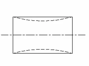
(3) The hydraulic plate bending machine is available with drum-shaped upper roll which is designed to offer high rigidity and minimized deformation. The upper roller is made using 42CrMo, and undergoes quenching and tempering after rough machining. Thus, it offers high hardness up to HB260-300, meeting the requirement of JB/ZG4289-86.
2. Lower Roller Assembly and Horizontal Motion Device
The lower roller assembly for the plate bending roll is made up of the lower roller, bearing seat, input gear, sliding bearing, etc.
(1) The sliding bearing of lower roller is made of SF-1 self-lubricating composite material.
(2) The horizontal motion device is powered by a motor, and the horizontal movement of upper roller is achieved with the help of worm and worm gear, worm gear box and lead screw. The horizontal movement of upper roll allows the 3 roll plate bending machine to realize asymmetric bending of metal plate.
(3) The bending force is provided by the main transmission device, and then, the power is transferred to lower rollers through output gear of main transmission, input gear of lower roller, and open gear transmission.
3. Support Roller Assembly
The assembly includes support roller, worm and worm gear, and wedge block. Our hydraulic plate bending machine is equipped with four groups of support rolls, with four rolls in each group. These rolls support vertical adjustment according to the load of feeding material.
4. Main Transmission Device
The transmission system of this sheet metal machinery involves the main motor, V-belt, cylindrical gear reducer, electro-hydraulic push rod brake, and more. The output gear is supposed to drive the gears of two lower rollers. The transmission system serves to provide the torque required for sheet metal bending through rotation in positive and negative directions.
5. Ejection Device
The unit is composed of the ram and the oil cylinder. The piston rod for the oil cylinder undergoes chromium coating treatment, ensuring long service life. The device allows our 3 roll plate bending machine to realize convenient collection of finished products.
6. Fixed, Tip-Over Racks, and Base
These components are all welding parts of steel. After welding, they are annealed to relieve stress, and shot peening is also applied. Two main oil cylinders are placed on fixed and tip-over racks, and the base adopts frame structure with high torque resistant factor. This base uses fewer anchor bolts, allowing easy installation and testing.
Our sheet metal bending machine has a special hydraulic system which consists of gear pump, valve group, hydraulic fitting and others.
(1) Superposition valve is adopted as the hydraulic valve, and the simple hydraulic system pipeline allows for convenient maintenance.
(2) The hydraulic system features overpressure protection and pressure regulating loop, synchronous loop, and speed loop.
(3) The pressure regulating loop regulates the working pressure of this system through main overflow valve, and the working pressure is 19.5MPa.
(4) The synchronous loop makes use of flow divider valve and throttle valve to realize preliminary synchronization for raise and descent of upper roll. A displacement sensor is utilized by our 3 roll plate bending machine for synchronization detection, and the positioning accuracy is ±0.15mm.
(5) The speed loop controls the tip over and reset actions of ejection device, and it is controlled by throttle valve.
(6) For proven safety, overflow valves are adopted for the pressure limit protections of the vertical movements of upper roll.
1. General description
(1) The hydraulic three roll plate bending machine supports 3-phase 4-wire power supply, and supports input voltage of 380V/50Hz. Its electrical system is comprised of electrical cabinet, operating console, and handheld button box.
(2) PLC system is applied for control circuit, and this reduces the utilization of circuit relays. Thus, the action is more reliable, and the service life is extended.
(3) Moreover, control buttons, indicators and programmable touch display are all set on the operating console.
2. Safety protections
(1) Motor is one crucial device for the hydraulic system, and it is equipped with circuit breaker and thermal relay for overcurrent protection and load protection, respectively.
(2) For all the actions of upper roll and ejection device, corresponding limit switches are adopted.
(3) In addition, shunt release is adopted, and two emergent stop buttons are set on operating console and tip-over rack respectively to cut off electricity under urgent situations.
These make sure our plate bending machine operate under safe conditions all the time.
3. Interlock functions
The hydraulic system of this metalworking machine also realizes different interlock functions.
(1) If the tip-over device has not been reset completely, all the movements of upper roll, lower roll and support roll are prohibited, and there is a limit switch for detection.
(2) When the upper roll is confirmed to be at the top position by corresponding limit switch, the horizontal motion of upper roll and individual descent of tip-over device are not allowed.
(3) If the working pressure of upper roll exceeds 1/3P as checked by pressure relay, the forward and backward movements of upper roll, and the vertical motion of support roll are both forbidden.
4. Failure indicator
The three roll plate bending machine is designed with failure indicators the warm the PLC system failure.
1. This sheet metal roll forming machine shows some excellent technical characteristics. The preset value of drum-shaped upper roll is determined on condition that the uniform load of roll is 70%, and the lower roll has a small diameter. There are adjustable support rolls under the lower roll, and these support rolls are designed to move vertically according to the sheet metal. In this way, the straightness of end product is improved to a large extent.
A: Bending thick plate
For thick plate, support rolls under lower roll moves upwards.
End product
As shown above, the value of t is low, and the straightness of end product is very high.
B: Bending thin plate
For thin plate, support rolls under lower roll moves downwards.
End product
The above shape is not possible to emerge, and the finished product shows high straightness.
2. This 3 roll plate bending machine adopts rear bending method which means that the direction of material feeding is opposite to that of upper roll motion. The down moving of upper roll and the rotation of lower roll are executed simultaneously, realizing continuous bending. The plate edge is directly pressurized for pre-bending, and this not only avoids clearance angle, but can also control the length and shape of remaining straight end.
Comparison between Our Product and Similar Ones
| Our product: 3 roll plate bending machine with universal purpose upper roll | Common products: three roll asymmetrical roll bending machines |
| The upper roll moves downwards whilst the lower roll rotates. | The plate edge is pre-bent first, then symmetrical bending is carried out. |
| The plate edge is directly pressurized for prebending. | The lower roll executes positive and negative rotations, and prebending is followed by bending treatment. |
| There is no clearance angle for the end product, and the flat end is on the standard circle, offering good circular degree. | For the finished product, clearance angle exists, and it is difficult to set the flat end on the standard circle. Thus, the circular degree is not comparable to the former one. |
Alignment Tolerance
This hydraulic plate bending machine adopts following measures to relieve misalignment for the end product.
1. Longitudinal sheet aligning device is adopted.
2. The geometrical tolerance of two lower rolls and central distance between them is considered as a key factor, and it is strictly monitored.
3. The synchronous movement of upper roll is electro-hydraulic controlled, employing feedback system.
4. The displacement sensor is used to detect the position of upper roll, and the controller is applied for comparison. The high level and low level signals are transferred to PLC to control the electromagnets of solenoid change-over valves on two ends of top roll. Then, the signal is compared continuously, and the synchronous accuracy is within ±0.20mm.
Bending Process
1. Sheet feeding and aligning
2. The upper roll moves to –X in horizontal direction, and descends to Y1. The lower roll rotates negatively to set steel plate at working position.
3. The lower roll carries out positive rotation whilst the upper roll moves downwards.
4. The upper roll moves down to Y2 and stops, and the lower roll keeps positive rotation.
5. The top roll moves to Y3 and stops, then, pressure is directly exerted on the plate edge for prebending.
6. The upper roll travels upwards to Y2-α, and to X horizontally. Then, it moves down to Y2, and the lower roll rotates positively.
7. The previous action stops at the plate edge, and the upper roll descends to Y3 to prebend plate edge directly.
8. The upper roll moves to X=0 and Y4, and the lower roll executes positive and negative rotations for compensation bending.
Cone Device
This cone device is a fitting for this sheet metal processing equipment, and it is mainly composed of shaft, hinge fulcrum, shaft sleeve, positioning pin, and swing oil cylinder. When bending cones, frictional resistance is generated between workpiece and shaft sleeve, and the shaft sleeve blocks the longitudinal motion of workpiece, progressively machining sheet metal into desired cone. The conicity is less than 30°, and the load capacity of workpiece is 30% bending capacity of this sheet metal bending machine.
However, this device is not necessary when the plate rolling machine is utilized for forming cylinders. Under this condition, please take out the positioning pin, and set the hinge fulcrum at horizontal direction with the help of swing oil cylinder, then, the positioning pin is fixed into location hole and locked.
This device is upgraded from similar product, and there is a large installation plane at the inner side of working roll. A blocking wheel is set on it to alter directions, and the wheel, seat size and central height can be changed according to practical needs. This device expands the application range of our 3 roll plate bending machine and improves cone quality.
Technical Parameters
| Model | Pressure of upper roll (ton) | Diameter of upper roll (mm) | Diameter of lower roll (mm) | Central distance (mm) | Motor power (kW) | ||
| Driving motor | Hydraulic motor | Motor for motion | |||||
| JW11S-12×2000 | 65 | 250 | 145 | 200 | 5.5 | 4 | 0.75 |
| JW11S-16×2000 | 75 | 255 | 150 | 245 | 7.5 | 4 | 1.1 |
| JW11S-16×2500 | 100 | 300 | 165 | 270 | 15 | 5.5 | 1.5 |
| JW11S-20×2000 | 100 | 290 | 160 | 270 | 15 | 5.5 | 1.5 |
| JW11S-20×2500 | 130 | 330 | 180 | 300 | 15 | 5.5 | 2.2 |
| JW11S-20×3000 | 160 | 375 | 200 | 330 | 18.5 | 7.5 | 2.2 |
| JW11S-25×2500 | 190 | 380 | 220 | 360 | 22 | 7.5 | 4 |
| JW11S-25×3000 | 230 | 410 | 235 | 380 | 30 | 11 | 4 |
| JW11S-25×3500 | 230 | 440 | 235 | 380 | 30 | 11 | 4 |
| JW11S-30×2500 | 230 | 410 | 235 | 380 | 30 | 11 | 4 |
| JW11S-30×3000 | 270 | 450 | 250 | 400 | 30 | 11 | 4 |
| JW11S-30×3500 | 320 | 480 | 260 | 420 | 37 | 15 | 5.5 |
| JW11S-30×4000 | 380 | 550 | 275 | 460 | 45 | 22 | 5.5 |
| JW11S-35×2500 | 320 | 450 | 260 | 420 | 37 | 15 | 5.5 |
| JW11S-35×3000 | 380 | 500 | 275 | 460 | 45 | 22 | 5.5 |
| JW11S-40×2500 | 380 | 500 | 275 | 460 | 45 | 22 | 5.5 |
| JW11S-40×3000 | 430 | 540 | 290 | 500 | 55 | 22 | 7.5 |
| JW11S-40×3500 | 540 | 580 | 330 | 610 | 55 | 22 | 11 |
| JW11S-40×4000 | 540 | 630 | 340 | 610 | 55 | 22 | 11 |
| JW11S-45×2500 | 430 | 520 | 290 | 500 | 55 | 22 | 7.5 |
| JW11S-45×3000 | 540 | 590 | 340 | 610 | 55 | 22 | 11 |
| JW11S-45×4000 | 610 | 660 | 360 | 650 | 75 | 30 | 15 |
Links:https://www.globefindpro.com/products/82943.html
-
 SC200/200 Construction Hoist
-
 CNC Hydraulic Swing Beam Shear
-
 Open Back Inclinable Press
-
 Copper Finned Tube
-
 Single Column Hydraulic Press
-
 Double Action Hydraulic Press
-
 Electric Control Box
-
 DIN 85-90
-
 3506_1E
-
 Carriage Bolt
-
 Mechanical 3-Roll Symmetrical Plate Bending Machine
-
 Sheet Metal Cut to Length Line
