Four Column Hydraulic Press
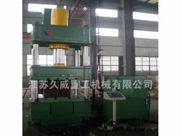
The JWY32 series four column hydraulic press is a universal purpose pressing machine. In addition to serving as metal forming equipment for sheet metal stamping, bending, and flanging purposes, it can also serve as the powder compacting press, plastic forming machine, and more by changing the tooling.
This machine press has an electrical system that is equipped with independent power system, and the centralized button control realizes three working modes, adjustment, manual and semi-automatic. The working pressure, pressing speed and slide stroke are all adjustable according to practical applications, and drawing, knocking-out, and machining without knocking-out are all applicable. These three processes are further divided into two modes which are constant-pressure mode and constant-stroke mode. The constant-pressure mode contains other functions after pressing, such as pressure holding, time delay, auto return, etc. Aside from these, the knock-out cylinder of this four column hydraulic press also possesses knocking-out, time delay, and auto return functions.
FeaturesWhen designing this hydraulic press, we take similar products fabricated by world-class manufacturers into consideration, and introduce their merits. Our product adopts industrial design and is optimized by finite element software, creating a modern design style focused on practicability, high rigidity, good reliability, durable performance as well as beautiful appearance.
This range of metal forming press is equipped with independent power system and electrical system, and uses circuit relay to accomplish adjustment and semi-automatic operation modes. The working pressure and slide stroke range can be adjusted depending on machining requirements, and the processing is at fixed pressure or fixed stroke. Hydraulic presses of fixed pressure mode are available with functions such as pressure holding, time delay and auto return after pressing step is finished.
Working Condition 1. Temperature: 0℃ ~40℃
2. Relative humidity: 55%-85%
3. Power supply: 3 phase, 380V±15%, 50Hz
4. Installation site: Clean place with little dust
5. Altitude: <1000m
Noise Measurement
1. LPA (sound pressure level): ≤ 82dB (A)
2. LWA (sound power level): ≤ 94dB (A)
Technical Parameters
| Item | Unit | Model | ||||||||||||||||
| JWY 32- 40A | JWY 32 -63 | JWY 32 -100 | JWY 32 -100A | JWY32-160 | JWY 32 -160C | JWY 32 -200 | JWY 32 -315 | JWY 32 -400 | JWY 32 -500 | JWY 32 -500C | JWY 32 -630 | JWY 32 -800 | JWY 32 -1000 | JWY 32 -1250 | JWY 32 -1600 | |||
| Rated pressure | kN | 400 | 630 | 1000 | 1000 | 1600 | 1600 | 2000 | 3150 | 4000 | 5000 | 5000 | 6300 | 8000 | 10000 | 12500 | 16000 | |
| Knock-out pressure | kN | 120 | 190 | 190 | 190 | 240 | 240 | 400 | 630 | 800 | 1000 | 1000 | 1000 | 1600 | 2000 | 2000 | 2000 | |
| Max. hydraulic pressure | MPa | 25 | 25 | 25 | 25 | 25 | 25 | 25 | 25 | 25 | 25 | 25 | 25 | 25 | 25 | 25 | 25 | |
| Slide stroke | mm | 350 | 450 | 600 | 600 | 700 | 700 | 700 | 800 | 800 | 900 | 900 | 900 | 800 | 900 | 900 | 900 | |
| Stroke ofknock-out cylinder | mm | 150 | 200 | 200 | 200 | 200 | 200 | 250 | 300 | 300 | 350 | 350 | 350 | 400 | 400 | 400 | 400 | |
| Max. distance betweenbottom of slide andworking table | mm | 700 | 800 | 900 | 900 | 1000 | 1000 | 1100 | 1250 | 1250 | 1500 | 1500 | 1600 | 1600 | 1600 | 1600 | 1600 | |
| Slide speed | Down | mm/s | 50 | 80 | 22 | 100 | 100 | 100 | 100 | 100 | 100 | 100 | 100 | 100 | 80 | 80 | 80 | 80 |
| Pressing | mm/s | 25 | 25 | 14 | 16 | 10 | 10 | 18 | 12 | 10 | 15 | 15 | 12 | 12 | 10 | 6-10 | 6-10 | |
| Return | mm/s | 50 | 80 | 50 | 80 | 50 | 50 | 80 | 60 | 45 | 80 | 80 | 50 | 50 | 50 | 45 | 40 | |
| Effective areaof table | Left-Right | mm | 500 | 560 | 720 | 720 | 750 | 1000 | 950 | 1250 | 1200 | 1400 | 2200 | 1500 | 1500 | 1530 | 1700 | 2000 |
| Front-Back | 460 | 500 | 580 | 580 | 640 | 800 | 900 | 1200 | 1100 | 1400 | 1400 | 1500 | 1500 | 1600 | 1600 | 1600 | ||
| Overalldimensionsof machine | Left-Right | mm | 1160 | 2400 | 2500 | 2500 | 2700 | 2700 | 2825 | 3235 | 3235 | 4060 | 6500 | 4200 | 4800 | 5250 | 5250 | 5800 |
| Front-Back | 900 | 1400 | 1500 | 1500 | 1700 | 1700 | 1500 | 1500 | 1500 | 1800 | 1800 | 2000 | 2000 | 2000 | 2500 | 4000 | ||
| Heightaboveground | 2250 | 3100 | 2950 | 3150 | 3400 | 3400 | 3725 | 4295 | 4500 | 4995 | 4740 | 5600 | 6000 | 6500 | 7000 | 6200 | ||
| Motorpower | kW | 5.5 | 7.5 | 7.5 | 7.5 | 7.5 | 7.5 | 18.5 | 18.5 | 18.5 | 37 | 37 | 45 | 75.5 | 75.5 | 90 | 90 | |
Major Components
This four column hydraulic press consists of main machine and control system, and these two parts form a whole structure with the help of pipelines and electrical devices. The main machine is made up of the machine body, main cylinder, stroke-limiting device and other components. The control system includes hydraulic station (power system), electrical cabinet, movable operation console, etc.
1. Machine Body
The hydraulic press machine body is comprised of the upper beam, slide, working table, hydraulic cushion, column, locknut, adjusting nut and more. The machining accuracy is controlled by adjusting nut and locknut fixed on the upper beam. The upper beam, slide and working table are all welded by high quality Q235-A steel plate through CO2 gas shielded welding, and then heat treatment is applied to relieve stress.
The main structural parts own flat surface without obvious unevenness, and the welding seam is polished to create smooth look without slag. All the structural parts are all optimized by finite element software, providing our four column hydraulic presses with excellent structural strength and rigidity.
2. Main Cylinder
The cylinder body is fixed inside the upper beam, and the lower end of piston is linked to slide by coupling flange and bolt. The piston head is used for guidance, and it is made of cast iron. Meanwhile, imported YX seal rings are mounted on the piston head while O rings are installed on the piston rod, and the cylinder is divided into two chambers. The cylinder has a guide sleeve that is equipped with O ring, and they are tightly locked by flange and bolts to ensure the sealing property. In addition, scraper seal is fixed on the flange to keep contaminates away from piston rod.
3. Slide
The slide is guided by 4 columns to realize vertical motion, and the guide sleeves between slide and columns are made from alloy. Thus, the guide sleeve shows excellent abrasive resistance, and the replacement is also very convenient. On the bottom surface of slide, there is a T slot which is used to fix dies, and its specification is predetermined or custom-made.
4. Hydraulic Cushion
The hydraulic cushion is positioned inside the base of the hydraulic press, and it is responsible for flanging treatment during drawing process. On the top of hydraulic cushion, there is a replaceable cushion for knock-out pin to avoid deformation and damage on the hydraulic cushion. Guided by guide post and guide sleeve, this hydraulic cushion shows stable running and high precision.
5. Knock-Out Cylinder
This four column hydraulic press is equipped with a piston type knock-out cylinder, and it is installed inside the central hole of working table. It is designed to control drawing and knocking-out of hydraulic cushion, and its body is made of 45# forged steel.
6. Column and Locknut
The column is constructed by 45# forged steel, and it undergoes quenching treatment. Its sliding surface receives mid-frequency hardening treatment, and the hardness reaches up to HRC42-50. On the other hand, the raw material for locknut is 35# forged steel, and it is processed by bluing. Furthermore, the column and locknut are connected together by thread.
7. Stroke-Limiting Device
The device is installed on the left side of the four column hydraulic press to control the slide stroke, and it contains shim, support, contactless travel switch, and other parts. Two shims are fixed on working table and upper beam respectively to hold angle iron, while there is guide slot on the support, and the slide stroke is controlled by travel switch.
8. Hydraulic Station
The hydraulic station is composed of motor, oil tank, axial plunger pump, 2-way cartridge valve, oil filter and air cleaner.
a. The oil tank is welded by Q235 steel plate, and pressure gauge and remote controlled overflow valve are installed on the front end for observing and adjusting pressure. Under the pressure gauge, there is a liquid level meter. Hence, user will find it very convenient to see the oil level. An oil filter is fixed on the oil suction to guarantee the cleanness of pump and hydraulic system, and the air cleaner is set on the oil tank to filter air. In addition, user can add oil after opening top cover, and the washing hole on the side facilitates the cleaning of oil tank.
b. Aside from above, the oil tank for our four column hydraulic press also receives shot blasting and rust prevention treatments. The air cleaner and valve block are set on the cover plate of oil tank in an ordered way, and plug screw is on the bottom to release oil or contaminants.
c. The main hydraulic pipelines are connected by flanges, and reasonably arranged pipe clamps are used to avoid vibration and leakage of the high-pressure pipeline. Before installation, the pipelines are processed with pickling and passivation. Thus, the oil won’t be contaminated.
d. Our hydraulic system adopts YCY14-1B axial plunger pump, and please refer to corresponding guide book for more information.
e. This four column hydraulic press takes advantage of 2-way cartridge valve, which mainly includes cartridges, cover plate, pilot valve and manifold block. The cartridges covers valve, spring, sealing element as well as valve bush, and the valve could be either cone valve or slide valve. The major function of this part is to control the oil direction, pressure and flow rate. The cover plate is composed of various built-in micro pilot control elements and other components, and its main purpose is to fix cartridges. The embedded pilot control elements work together with pilot valve to control the working state of cartridge valve. The cover plate is divided into three types, which are direction control type, pressure control type, and flow rate control type. As for pilot valve, it is installed on cover plate to control the action of cartridges, and its component is standard solenoid change-over valve. The manifold block is designed to mount cartridge, cover plate and other control valves, and it can also connect main oil way and control oil way.
Hydraulic System
The hydraulic system is mainly comprised of energy conversion devices (pump and oil cylinder) and energy transmission devices (oil tank and pipeline). It supplies power for the movements of slide, and this process is controlled by electrical system.
This hydraulic system adopts double-pump oil supply system and mass flow cartridge valve, and there is an oil filter at the oil suction to keep contaminants away, enabling normal working of the system. This system also comes with air cleaner, indicators for oil level and oil temperature, and more.
Our hydraulic press is equipped with hydraulic safety loop in the lower chamber of main oil cylinder. Thus, the slide won’t be out of control and drop down freely. Additionally, slide inching is achieved simply by pressing relevant buttons.
Electrical System
This four column hydraulic press has one independent electric control cabinet and one movable button station.
The electric control cabinet is primarily used to install power control devices, such as power supply controller, motor starting controller, protection switch, leakage protector, etc. Ventilating facility is placed inside the cabinet, and dust won’t get into the cabinet easily due to its excellent sealing property. Please be noted that the location of electric control cabinet is determined by the user, and user must offer written notice before production.
The operation station is equipped with many buttons and indicators, such as operation buttons, function switches, start and stop buttons for motors, as well as monitoring and alarming indicators. As a result, the operator is able to get control of the working status at any time.
On the movable button station set return, two-hand pressing, emergency stop and other buttons, and there are corresponding rotary knobs on the operation station. Thus, misoperation is effectively avoided. Moreover, the power supply for this hydraulic press is 380VAC/50Hz, the control power supply is 220VAC, and the power supply for pilot valve magnet is 24VDC.
Operation Systems
1. Adjustment (inching): Press relevant button for one time to carry out one inching action, and this is mainly used during machine testing and die replacement.
2. Manual: The user should press operation buttons to accomplish corresponding action, and the movement will come to a halt if stop button is pressed or the moving part reaches to limiting position.
3. Semi-automatic: The movable control station requires two-hand pressing, which means that two buttons should be pressed at the same time to execute one processing step. The actions of semi-automatic process are as follows: fast descent of slide – slow pressing – pressurizing, time delaying and releasing pressure – slide returning – hydraulic cushion knocking-out and demoulding.
4. The slide stroke is adjusted by travel switch, the pressure of main cylinder is regulated by remote controlled pressure regulating valve, and the pressure holding time is set by time relay.
Safety Protection
1. Stop and emergency stop buttons: Please press stop button to stop action when abnormal working occurs, and if emergency stop button is pressed, this hydraulic press will stop completely including motor.
2. Two-hand operation: The time interval between pressing actions of two hands should be within 0.5s~1s.
3. Secondary support loop: It is in the lower chamber of main cylinder, and the single failure of any primary support loop won’t lead to the drop of slide.
4. Safety valve is equipped for the hydraulic system.
Links:https://www.globefindpro.com/products/82957.html
-
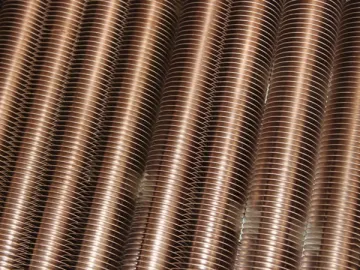 Copper-Nickel Finned Tube
-
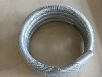 Aluminum Finned Tube Condenser
-
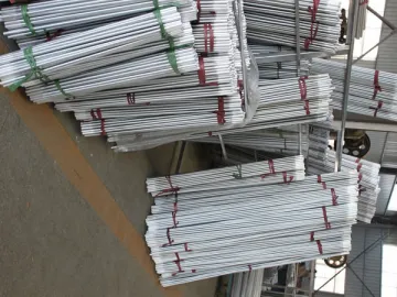 Aluminum Finned Tube
-
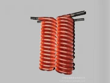 27.5 Medium-High Copper Finned Tube
-
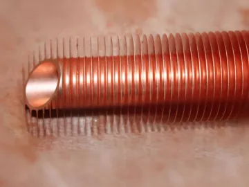 47 High Copper Finned Tube
-
 57 Bimetallic High Finned Tube
-
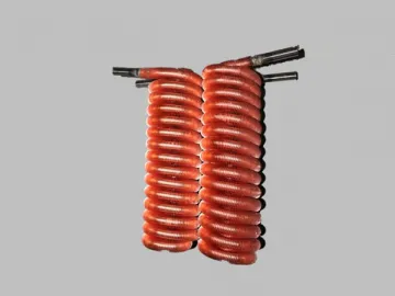 Copper Finned Tube Condenser
-
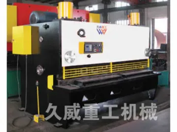 Hydraulic Guillotine Shear
-
 Sheet Metal Shear
-
 Bimetallic Finned Tube (Steel & Aluminum)
-
 Double Action Hydraulic Press
-
 Single Column Hydraulic Press
