GW22A High Voltage Disconnector
1. Product Overview
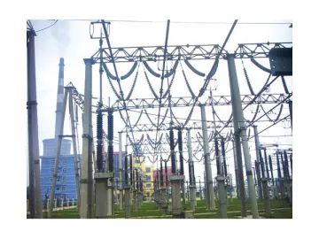
a. The GW22A-126/145/252Ⅱ/363/550 series of high voltage disconnector includes three monopoles and each monopole has a single-column structure. It is used for the switching of high voltage lines under no load and for the electrical isolation of high voltage busbar or electrical equipment like circuit breaker, which is to be maintained, from high voltage lines.
b. Our high voltage disconnector mainly consists of the base, post insulator, rotating insulator, main switch, and the static contact of the main switch. The post insulator and rotating insulator are mounted on the base. The main switch is mounted on top of the insulators and the static contact is mounted on the transmission bus.
c. The main switch has a single arm folding structure. During opening, it is pulled downwards and folded, forming an insulation fracture in the vertical direction with the above static contact. During closing, the switch is pushed up so that the moving contact clamps the static contact, thereby finishing closing operation.
d. It is convenient to configure a JW7 earthing switch for the GW22A high voltagedisconnector. Between the two, a mechanical interlocking device is set.
e. The main switch and earthing switch of GW22A-126 and GW22A-145 are equipped with electric operating mechanism. Manual mechanism can also be adopted as per the requirements of the customers. The main switch of GW22A-252 is equipped with electric mechanism and the earthing switch with manual one. The earthing switch can also be equipped with the electric mechanism as per customer needs. GW22A-363 and GW22A-550 are equipped with electric mechanisms.
f. Through the connecting rods between the monopoles, three-pole mechanical linkage is achievable (three-pole electrical linkage for the GW22A-363 and GW22A-550).
2. Product Classification
a. Divided by voltage level: 126 kV, 145 kV, 252 kV, 363 kV, 550 kV;
b. Divided by current level: 1600A,2000A, 2500A, 3150A,4000A,5000A;
c. Divided by whether there is a grounding switch: Not grounded, grounded.
d. Divided by arrangement way: 45° arrangement, 135° arrangement, one-row arrangement
Table 1
| Model | GW22A-126 | GW22A-145 | GW22A-252Ⅱ | ||||||||||||
| Rated voltage kV | 126 | 145 | 252 | ||||||||||||
| Rated current A | 1600 | 2000 | 2500 | 3150 | 1600 | 2000 | 2500 | 3150 | 1600 | 2000 | 2500 | 3150 | 4000 | 5000 | |
| Rated peak withstand current kA | Disconnector | 100, 125 | 100, 125 | 100, 125, 160 | |||||||||||
| Earthing switch | 100, 125 | 100, 125 | 100, 125, 160 | ||||||||||||
| Rated short-time withstand current and rated short-circuit duration kA s | Disconnector | 40, 4 50, 3 | 40, 4 50, 3 | 50, 3 63, 3 | |||||||||||
| Earthing switch | 40, 4 50, 3 | 40, 4 50, 3 | 50, 3 63, 3 | ||||||||||||
| Rated 1min power frequency withstand voltage (rms) kV | To earth | 230/260* | 285/325* | 460/552** | |||||||||||
| Between fractures | 300/340* | 330/375* | 605/726** | ||||||||||||
| Rated lightning impulse withstand voltage (peak) kV | To earth | 550/625* | 660/750* | 1050/1260** | |||||||||||
| Between fractures | 650/740* | 760/860* | 1250/1500** | ||||||||||||
| Rated switching impulse withstand voltage (peak) kV | To earth | - - | - - | - - | |||||||||||
| Between fractures | - - | - - | - - | ||||||||||||
| Opening and closing bus switching current | Breaking current A | 2500 | 2500 | 2500 | |||||||||||
| Switching voltage V | 427 | 427 | 427 | ||||||||||||
| Breaking times | 100 | 100 | 100 | ||||||||||||
| Capacitive current opened and closed (phase voltage) A | 1, 2 | ||||||||||||||
| Inductor current opened and closed (phase voltage) A | 0.5, 1 | ||||||||||||||
| Radio interference level | ≤500μV | ||||||||||||||
| Mechanical life | 3000 times | ||||||||||||||
| Rated terminal static mechanical load N | Horizontal longitudinal | 1250 | 1500 | 2000 | |||||||||||
| Horizontal transverse | 750 | 1000 | 1500 | ||||||||||||
| Vertical | 1000 | 1250 | 1250 | ||||||||||||
| Nominal contact area mm | Longitudinal displacement | 350 | 350 | 500 | |||||||||||
| Horizontal offset | 350 | 350 | 500 | ||||||||||||
| Vertical offset | 200, 300 | 200, 300 | 250, 450 | ||||||||||||
Table 2
| Model | GW22A-363 | GW22A-550 | ||||||||
| Rated voltage kV | 363 | 550 | ||||||||
| Rated current A | 1600 | 2000 | 2500 | 3150 | 4000 | 5000 | 3150 | 4000 | 5000 | |
| Rated peak withstand current kA | Disconnector | 125, 160 | 125, 160 | |||||||
| Earthing switch | 125, 160 | 125, 160 | ||||||||
| Rated short-time withstand current and rated short-circuit duration kA s | Disconnector | 50, 3 63, 3 | 50, 3 63, 3 | |||||||
| Earthing switch | 50, 3 63, 3 | 50, 3 63, 3 | ||||||||
| Rated 1min power frequency withstand voltage (rms) kV | To earth | 510/653*** | 740**** | |||||||
| Between fractures | 510 ( 210)/653 ( 269)*** | 740 ( 315)**** | ||||||||
| Rated lightning impulse withstand voltage (peak) kV | To earth | 1175/1504*** | 1675**** | |||||||
| Between fractures | 1175 ( 295)/1504 ( 378)*** | 1675 ( 450)**** | ||||||||
| Rated switching impulse withstand voltage (peak) kV | To earth | 950/1140*** | 1300**** | |||||||
| Between fractures | 850 ( 295)/1088 ( 378)*** | 1175( 450)**** | ||||||||
| Opening and closing bus switching current | Breaking current A | 2500 | 2500 | |||||||
| Switching voltage V | 427 | 427 | ||||||||
| Breaking times | 100 | 100 | ||||||||
| Capacitive current opened and closed (phase voltage) A | 1, 2 | 3 | ||||||||
| Inductor current opened and closed (phase voltage) A | 0.5, 1 | 2 | ||||||||
| Radio interference level | ≤500μV | |||||||||
| Mechanical life | 3000 times | |||||||||
| Rated terminal static mechanical load N | Horizontal longitudinal | 2500 | 4000 | |||||||
| Horizontal transverse | 2000 | 2000 | ||||||||
| Vertical | 1500 | 2000 | ||||||||
| Nominal contact area mm | Longitudinal displacement | 500 | 600 | |||||||
| Horizontal offset | 500 | 600 | ||||||||
| Vertical offset | 250, 450 | 400, 500 | ||||||||
Note: a. For the data marked with "*", the number before "/" is the parameter value measured at an altitude of 2000 m and the number after "/" is the parameter value measured at an altitude of 1000 m;
b. For the data marked with "**", the number before "/" is the parameter value measured at an altitude of 2500 m and the number after "/" is the parameter value measured at an altitude of 1000 m;
c. For the data marked with "***", the number before "/" is the parameter value measured at an altitude of 3000 m and the number after "/" is the parameter value measured at an altitude of 1000 m;
d. For the data marked with "****", they are obtained at an altitude of 1000 m.
4. Service and Installation Conditions
Ambient temperature: -50℃~ 50℃;
Altitude:≤ 2000m for GW22A-252, ≤ 3000m for GW22A-363
Wind pressure: ≤ 700Pa;
Seismic intensity: ≤ Mercalli IX;
Ice thickness: ≤ 20 mm;
Pollution class: class III and IV;
There should be no inflammable, explosive, corrosive materials or violent vibration in the mounting site.
Related Names
Safety Electrical Switch | Disconnecting Switch | HV Circuit Isolator
Links:https://www.globefindpro.com/products/85223.html
-
 10~35kV Oil Immersed Distribution Transformer
-
 Dry Type Transformer
-
 35~220KV Oil Immersed Current Transformer
-
 35~220KV SF6 Voltage Transformer
-
 35~220KV Capacitor Voltage Transformer
-
 10~750kV Oil Immersed Power Transformer
-
 35kV Furnace Transformer
-
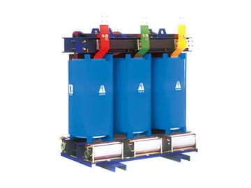 Dry Type Cast Resin Transformer
-
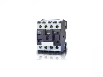 CJX2 AC Contactor
-
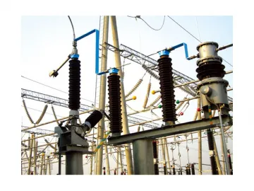 Transformer Neutral Point Protection Device
-
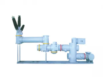 126/145KV Three Phase Gas Insulated Switchgear (GIS)
-
 TK-FC High Voltage Dynamic Var Compensator

