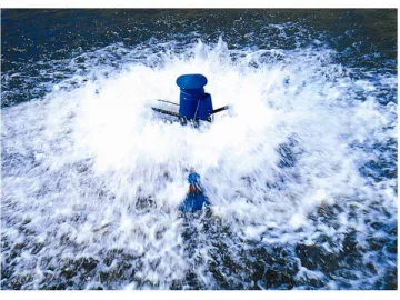
Impeller Aerator
Impeller Aerator
Through years’ trackingsurveys and data analysis, we found that the most damageable parts of impelleraerator are electric motor and gears. In this regard, our product has beenspecially improved on these two parts.
Technical Parameters
| Model | Power KW | voltage V/50Hz | Oxygen transfer capacity kgo2/h | Power efficiency Kg02/kwh | Loading Area | 20Container Set |
| YL-3 | 3 | 380 | ≥4.5 | ≥1.5 | 8-12 | 80 |
| YL-1.5 | 1.5 | 380 | ≥2.3 | ≥1.5 | 4-8 | 80 |
| YL-1.5 | 1.5 | 220 | ≥2.3 | ≥1.5 | 3-6 | 85 |
| YL-1.1 | 1.1 | 220 | ≥1.6 | ≥1.4 | 3-4 | 85 |
| YL-0.9 | 0.9 | 220 | ≥1.2 | ≥1.4 | 1-3 | 85 |
Our impeller aerator has a overheating and overload protector inside. Once themain power voltage is too low or the heat is accumulated too much the switchwill turn off automatically avoiding the accident burning.
The gears we adopt for our product are made of chromium manganese titaniumalloy steel and the surfaces of the gears are carburization processed which canadditionally prolong the service life of gears.
We take advantage of the patent non-fabricated impellers and these kind of impellers can run without off centering and can beportable. Upon the request of different service environment and customer, wedevelop the engineering plastic type and stainless steel type for customer’soption in order to make our impeller aerator able to be long-term used inseawater or corrosive industrial waste water without frequent replacingimpeller
The motor cover canprevent leaking water into the motor, in this regard, we remove the risk ofmotor being burning out.
Links:https://www.globefindpro.com/products/88131.html
-
 Kitchen Appliance and Accessories
-
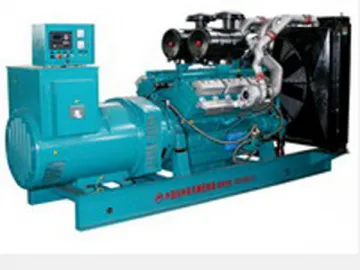 90-500KW Open Type Diesel Generator powered by Tongchai Engine
-
 Steel Baskets
-
 High Efficiency Paddlewheel Aerator(Air Cooling)
-
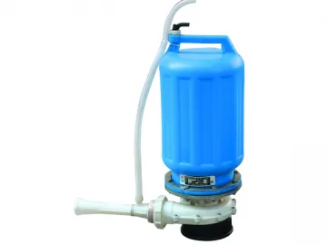 Jet Aeration Floating Pump
-
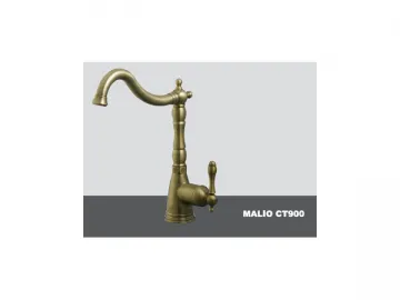 Faucet
-
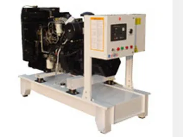 20-120KW Lovol Engine Diesel Generator
-
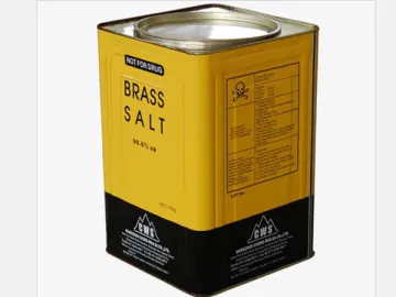 Tinplate Barrel of Chemical Raw Materials
-
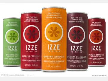 Juice Tin Can
-
 Beer Can
-
 Sports Drink Tin Can
-
 Classification by Product Shape
