LED Display User Manual
LED Display User Manual
Testelectricity by one cabinet
1, Select power supply voltage
The power voltage in different countries may vary, so please choose the rightvoltage mode, namely 220V or 110V.
Notice: The power supply will burn out if the voltage needs 220V, but the power switch is on 110V side.
2, Connect the power cable
4 mm2 power supplycable is a three core cable (Red, Green, and Yellow ). The redcable connects L, the yellow one connects earth, and the green one connects N.After the power supply cable is connected, please test the circuit usingammeter. You can switch on the Electricity button if there is no short circuit.After this, in the normal circumstances, the LED display does not showanything, but the switching power supply is lighting, and the indicator red lightof receiving card is on.
About the Control System
The entire screen doesn’t turn or has checks.
Whether the control host machine starts.
The display is in the state ofscreen saver, being blue screen or black screen.
Check whether the communication green lights of sending card andreceiving card have flicker.
Whether the communication line isinserted well.
Whether the sending card is inserted well.
Whether the data lines betweenmulti-media card and collection card/sending card and receiving card areconnected well.
The switch position of receiving card JP1 or JP2 is wrong.
Start the host machine
Insert the communication line well
Insert the sending card again.
Adjust the position of JP1 and JP2 switch well.
AboutDisplay Screen
1. The entire screen is not light
Check whether the voltage of power supply matches thevoltage needed by display screen.
Check whether the power supply connects the signalline.
Check whether the test card has recognition interface,while the flicker of red light for test card doesn’t have recognition, checkwhether the light board and test card have the same powerground, or whether the interface of light board hasshort circuit with the ground, which leads that the interface can't beidentified.
Check whether 74HC245 has short circuit with insufficient solder, whether theinput and output pin of enable (EN) signals corresponding to 245 haveinsufficient solder or short circuit to the other circuits.
Note: mainly check the power supply and enable (EN)signal.
2. Regular interleave without light displays overlapping picture (only forscanning screen) when taking point oblique scan.
Check whether the input openings of A, B, C, Dsignal and 245 have broken line, insufficient solder, short circuit.
Test whether the output ends of A, B, C, D corresponding to 245 and 138 have broken line, insufficientsolder, short circuit.
Test whether each signal of A, B, C, D has the short circuit or thecertain signal has the short circuit to the ground.
TreatmentProcedure for Common Faults of LED Display (1)
1. Confirm that your display screen is a synchronous screen orasynchronous screen. The display of synchronous screen depends on the settingof display, while the asynchronous screen doesn’t rely on this.
2. Confirm whether your display screen is partial display problem or the entirescreen problems:
If it is partial display problem, you can get rid of it on communicationaspect. This problem may be caused by the hardware of display screen.
If the entire screen displays abnormally, there are many reasons for it:
For synchronous screen, please check the setting ofdisplay, the communication, the sending, and then the receiving.
For asynchronous screen, firstly check the parameters of display screen, suchas hardware address, width, height, and confirm whether the IP changes. Ifthese parameters are right, then test the communication, and finally confirmthe control of display screen.
Treatment Procedure forCommon Problems of LED Display (2)
1. Promptthat the COM opening of control system can’t be found when starting up LEDstudio each time.
The signal collection line between data sending card is not connected orthe COM opening of the computer is damaged; or the driver of COM opening is notinstalled; or the contact of data line is poor.
Change data line or serial port.
2. The entire screen for every 16 line data flashes or often lights.
Check the setting of LED studio
Open LED studio to open debugging-hardware setting (passwords 168)-systemsetting, set the line sequence to be 0 or 1.
3. The picture of entire screen wobbles or has double image.
Check the communication line between the computer and large screen
Check the DVI line of multi-media card and sending card.
The sending card is damaged.
Insert the communication line again or change it; insert DVI line againfor fixing; change the sending card.
5. The entire screen has blurred screen and streak phenomenon.
Check the sending card, choose the default setting, send data firstly, and then save the data.
Check the setting parameters, set the data again
Treatment Procedure for Common Problems of LED Display (3)
Note: mainly check the signals of ABCD lines.
1. All lines are light or, one or several linesare not light.
Check if the lines between 138 and 4953 have the broken lines,insufficient solder, short circuit.
2. Two lines or several lines (generally it is the multiple of two, whichhas regularity) are light at the same time when scanning.
Test whether it has short circuit between each signal of A, B, C, D.
Test whether the 4953 output end has short circuit with other outputends.
3. There is a single point or multipoint which is not light withoutregularity when all are light.
Firstly, find out whether the corresponding control pin measurement ofthis module has short circuit with this line.
Change module or single light.
4. There is one row or several rows which is not light when all arelight.
Find out the lead foot of controlling this row on the module, checkwhether the driver IC(74HC595/TB62726...) connects theoutput end.
5. There is a single point or a single row or the whole line which islight without control.
Check whether this row has short circuit with power ground.
Test whether this line has short circuit with positive pole of powersupply.
Change its driver IC.
6. The display is disordered, but the signal which is outputted to thenext board is normal.
Treatment Procedurefor Common Problems of LED Display (4)
Test whether the output end of STB lock and saving corresponding to 245connects the lock and saving end of driver IC or the signal comes to the othercircuit because of short circuit.
1. The display is disordered and the output is abnormal.
Test whether STB signal of CLK lock and saving has shortcircuit.
Test whether the CLK of 245 has input and output.
Test whether the clock signal has short circuit to theother circuits.
Note: mainly test the clock and lock and saving signals.
2. Display lack of color
Check whether the data end of this color for 245 has inputand output.
Check whether the data signal of this color has short circuit to the othercircuits.
Check whether concatenation data opening between the driver IC of this color has the broken line, insufficientsolder, short circuit.
Note: it is easy to find the problem by using voltage examination method,examine whether the voltage of data opening is different from the normalvoltage to confirm the fault area.
3. Output has some problems
Check whether the line from the output interface andsignal output IC is connected or has short circuit.
Check whether the clock lock and saving signal at outputopening is normal.
Check whether concatenation output data opening between the last driver IC connects with data opening of output interface or hasshort circuit.
Whether the output signal has mutual short circuit or hasshort circuit to the ground.
Check whether the flat cable of output is good.
Links:https://www.globefindpro.com/products/91874.html
-
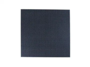 P8 SMD Outdoor Color LED Display Screen
-
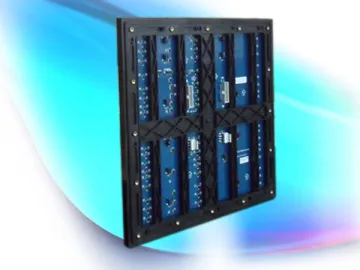 P6.67 SMD Outdoor Full Color LED Display Screen
-
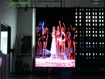 Soft LED Screen
-
 Black Diamond LED Display Screen
-
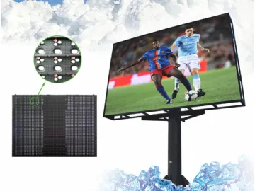 Hollowed LED Display Screen
-
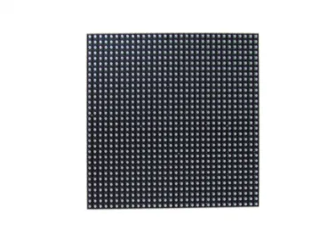 P4 SMD Indoor Full Color LED Display Screen
-
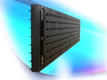 P16 Ventilation LED Display Screen
-
 Steel Pipe Blind Flange
-
 Neck Steel Pipe Flange
-
 Steel Pipe
-
 Pipe Fittings Steel Tee
-
 Steel Pipe Orifice Flange


