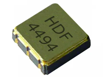
915MHz SAW Filter
915MHz SAW Filter
HDF915ASMD-4
Scope
This specification covers the characteristics ofSAW filter with 915MHz centre frequency.
Table 1
Electronic Characteristics of 915MHz SAW Filter
| Item | Specification |
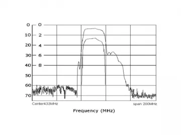
| Center Frequency (fo ) | 916 MHz |
| Insertion Loss(dB) 1) 915-917 MHz 2) 871-875 MHz 3) 893-896 MHz 4) 9 36-939 MHz 5) 957-962 MHz | 4.5max 40 min 30 min 20 min 40 min |
| Ripple Deviation (915-917MHz) (dB) | 1.5max |
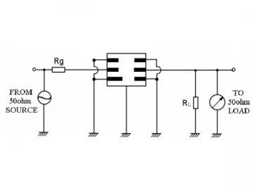
| Input/Output Impedance (Nominal) | 50 Ω |
Marking of 915MHz SAW Filter
HD F916A
Color-Black or Blue
916-Center Frequency (MHz)
Performance-Application Low-Loss SAW filter of cordless system, Centerfrequency 916 MHz
Maximum Rating of 915MHz SAW Filter
| Operation Temperature Range | -10 ℃ to 50℃ |
| Storage Temperature Range | -40 ℃ to 85℃ |
| DC. Permissive Voltage | 0 V DC. max . |
| Maximum Input Power | 5dBm |
EnvironmentalCharacteristics of 915MHz SAW Filter
1. High temperature exposure
Placing the 915MHz SAW filter at 85 ℃ for sixteen hoursand then releasing the filter into a room with normal temperatureconditions for twenty-four hours prior to the measurement, it shall fulfil thespecifications in table 1
2. Low temperature exposure
Placing the 915MHz SAW filter at -20 ℃ for sixteen hoursand then releasing the device into a room with normal temperatureconditions for twenty-four hours prior to the measurement, it shall fulfil thespecifications in table 1
3. Temperature cycling
The 915MHz SAW filter must be in a place with lowtemperature, -40 ℃ for 30 minutes, following by a hightemperature of 25℃ for fiveminutes and then a higher temperature of 85℃ for30 minutes. When the device is released into a room with normal temperatureconditions for 1 to 2 hours prior to the measurement, it shallmeet the specifications in table 1.
4. Resistance tosolder heat
If the 915MHz SAW filter terminals are immerse no closer than 1.5 mm into the solder bath at 260℃ ±10℃ for 10±one second an then release itinto a room with normal temperature conditions for four hours, it shall meet thespecifications in table 1.
5. Solderability
Submerge the device terminals into the solder bath at 245℃ ±5℃ for five seconds. More than 95% area of the soldering pad must be covered withnew solder; the 915MHz SAW filter shall meet thespecifications in table 1.
6. Mechanicalshock
Drop the 915MHz SAW filter randomly onto the concrete floor from aheight of 1 m threetimes. The filter shall fulfil the specifications in table 1.
7. Vibration
Subject the device to vibration for two hours each in x, y and z axeswith amplitude of 1.5 mm at 10 to 55 Hz. The filtershall fulfil the specifications in table 1.
8. Lead fatigue
(1) Pulling test
If a vertical weight (1Kg)is applied to the 915MHz SAW filter along with the direction of lead without any shock for fiveor ten seconds, the device shall satisfy all the initial characteristics.
(2) Bending test
The 915MHz SAW filter shall be subjectto withstand against 90º bending with 450g weight in the direction of thickness.This operation shall be done toward both directions; the deviceshows no evidence of damage and shall satisfy all the initialelectrical characteristics.
Remarks for 915MHz SAW Filter Usage
1. Static voltage
Please avoid static voltagebetween signal load and ground, it may cause deteriorationor destruction of the SAW filter components.
2. Ultrasonic cleaning
Please avoid ultrasonic cleaning, it may cause deterioration ordestruction of the SAW filter components.
3. Soldering
Please avoid soldering different parts of the SAW filter components, just leads may be soldered.
Packing of 915MHzSAW Filter
1. Dimensions
(1) Carrier Tape: Figure 1
(2) Reel: Figure 2
(3) The 915MHz SAW filtershall be packed properly to avoid damage during transportation or storage.
2. Reeling Quantity
1000 pieces/reel 7’’
3000 pieces/reel 13’’
3. Taping Structure
(1) The tape shall be wrappedaround the reel in the direction shown below.
(2) Label
| Device Name |
|
| User Product Name |
|
| Quantity |
|
| Lot No. |
|
(3) Leader part andvacantposition specifications.
TapeSpecifications of 915MHz SAW Filter
1. Tensile Strength of Carrier Tape:4.4N/mm width
2. Top Cover Tape Adhesion(See the belowfigure)
(1) Pull off angle: 0~15º
(2) Speed: 300mm/min.
(3) Force: 20~70g
[Figure 1] Carrier Tape Dimensions
[Unit: mm]
| W | F | E | P0 | P1 | P2 | D0 | D1 | t1 | t2 | A | B |
| 12.00 ±0.30 | 5.50 ±0.10 | 1.75 ±0.10 | 4.00 ±0.10 | 8.00 ±0.10 | 2.00 ±0.10 | Ø1.50 | Ø1.0 ± 0.25 | 0.25 ±0.05 | 1.65 ±0.10 | 4.04 ±0.10 | 4.10 ±0.10 |
[Figure 2]
[Unit: mm]
| A | B | C | D | E | W | t | r |
| Ø 330 ± 1.0 | Ø 100 ±0.5 | Ø 13 ±0.5 | Ø 21 ±0.8 | 2 ±0.5 | 13 ±0.3 | 3 max. | 1.0 max. |
Shoulder is a specialized 915MHz SAW filter manufacturer in China. Ourcompany provides a wide range of products, including SAW resonator, crystalresonator, Pico repeater, WiFi module, and others.
Links:https://www.globefindpro.com/products/92785.html
