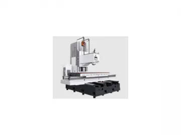
Vertical Machining Center VMC2180S, VMC21100S, VMC2580S
3 Axis structure configurations
All axes adopt precision ball screws of 63 mm. diameter, and special bearings. Well engineered design of structure. The machine structure is well configured and logically laid out, and the main components such as the bed, the column, etc., all incorporate thermally symmetrical design and reinforced cast box-type structure, all of which ensures that the machining center can perform at high speed, with high efficiency and high accuracy. Also, the user interface is friendly and makes the machine easy to operate.
Assurance of headstock stability
Headstock is equipped with oil cooler to cool the spindle and gearbox for reducing the parts' thermal deformation, keeping the consistency of the accuracy.
The vertical machining center is equipped with a hydraulic station to ensure the accuracy of spindle releasing-clamping tool and shifting travel, the operating stability under high step or low step, and larger output torque.
Spindle with powerful output torque
Double-speed gears with high accuracy provide low speed large torque under heavy cutting. The standard output torque of the spindle is 560Nm, and the max output torque is 990Nm.
Super-Heavy-Load bed models
VMC2180S and VMC21100S incorporate box-style cast-iron guideways on all 3 axes, for a maximum work-piece load weight of 3000 kg. The super-wide cast iron high strength bed has 4 hardened guide-ways to meet the requirements of heavier work-pieces.
Model VMC2580S 8 box ways, 4 linear guideways The X-axis has 8 bearing blocks, and the Y-axis has 4 guideways, and this combined with the high-rigidity box type structure of the machine, renders excellent heavy cutting performance with high accuracy.
Technical Specifications of Vertical Machining Center
| Item Unit | VMC2180S | VMC21100S | VMC2580S | ||||||
| Worktable | Worktable dimensions | mm | 2000×800 | 2200×1000 | 2700×800 | ||||
| T-slot sizes | mm×N | 22×5 | 22×5 | 22×5 | |||||
| Max. load allowed | kg | 3000 | 3000 | 3000 | |||||
| Machining range | Max. travel of worktable - X axis | mm | 2100 | 2100 | 2500 | ||||
| Max. travel of slider - Y axis | mm | 800 | 1000 | 800 | |||||
| Max. travel of spindle - Z axis | mm | 850 | 850 | 850 | |||||
| Distance from spindle endface to worktable face | Max. | mm | 1050 | 1050 | 1050 | ||||
| Min. | mm | 200 | 200 | 200 | |||||
| Spindle | Taper bore (7:24) | BT50 | BT50 | BT50 | |||||
| Speed range | r/min | 20-4500 | 20-4500 | 20-4500 | |||||
| Max. output torque | Nm | 560 | 560 | 560 | |||||
| Spindle motor power | kW | 22/26 | 22/26 | 22/26 | |||||
| Spindle axial resistance | N | 12250 | 12250 | 12250 | |||||
| Distance from spindle nose to worktable | mm | 1040 | 1040 | 1040 | |||||
| Feed | Rapid speed | X axis | m/min | 15 | 15 | 15 | |||
| Y axis | m/min | 15 | 15 | 15 | |||||
| Z axis | m/min | 10 | 10 | 10 | |||||
| Feed speed | m/min | 4 | 4 | 4 | |||||
| 3-axis drive motor (X/Y/Z) | kW | 6/6/7 | 6/6/7 | 6/6/7 | |||||
| Tool magazine | Tool magazine form | Chain-type | Chain-type | Chain-type | |||||
| Tool magazine capability | pcs | 32 | 32 | 32 | |||||
| Max. tool length | mm | 350 | 350 | 350 | |||||
| Max. tool weight | kg | 15 | 15 | 15 | |||||
| Diameter of max tool pan Full/Adjacent station empty | mm | φ125/φ190 | φ125/φ190 | φ125/φ190 | |||||
| Tool change time (tool-to-tool) | s | 3.5 | 3.5 | 3.5 | |||||
| Positioning accuracy | Perform the standard | JISB6330 | JB/T8771.4-1998 | JISB6330 | JB/T8771.4-1998 | JISB6330 | JB/T8771.4-1998 | ||
| X axis | mm | ±0.008/300 | 0.022 | ±0.008/300 | 0.022 | ±0.008/300 | 0.025 | ||
| Y axis | mm | ±0.008/300 | 0.016 | ±0.008/300 | 0.020 | ±0.008/300 | 0.020 | ||
| Z axis | mm | ±0.008/300 | 0.020 | ±0.008/300 | 0.020 | ±0.008/300 | 0.020 | ||
| Repeatability | X axis | mm | ±0.005 | 0.013 | ±0.005 | 0.013 | ±0.005 | 0.013 | |
| Y axis | mm | ±0.005 | 0.012 | ±0.005 | 0.012 | ±0.005 | 0.012 | ||
| Z axis | mm | ±0.005 | 0.012 | ±0.005 | 0.012 | ±0.005 | 0.012 | ||
| General power capacity | KVA | 65 | 65 | 65 | |||||
| Overall dimension (L×W×H) | mm | 7430×4250×4373 | 7430×4250×4373 | 8150×3800×4580 | |||||
| Machine weight | kg | 28000 | 29000 | 31000 | |||||
| CNC system | FANUC 0i-MD | FANUC 0i-MD | FANUC 0i-MD | ||||||
Note: The parameters in the list are for reference only, please subject to material object.
Standard Accessories
Chain-type tool magazine
Coolant system
Pneumatic system
Work-area light system
3-Color alarm lamp
Adjust table leveling pads
Anchor bolts
Fan for electrical cabinet
Automatic lubrication system
Fully-enclosed workspace
Stainless-steel telescopic guideway
Covers
Fanuc 0i CNC system
Optional Accessories
Manipulator-type tool magazine
Air condition
IV-axis rotary table
Yielding water for spindle center
3-axis sealed encoder
Tool measuring device
Workpiece measuring device
Links:https://www.globefindpro.com/products/96303.html
-
 Slant Bed CNC Lathe, HTC32, HTC45, HTC54 Series
-
 Slant Bed CNC Lathe, HTC16
-
 Conventional Lathe CA Series
-
 Horizontal CNC Lathe ETC-h Series
-
 Slant Bed CNC Lathe, HTC32n
-
 CNC Milling Boring Machine, GMC Series Gantry Type
-
 Slant Bed CNC Lathe, HTC50t, HTC63t, HTC80t, HTC100t
-
 Flat Bed CNC Lathe, CAK16/36/40 Series
-
 Slant Bed CNC Lathe, HTC1608
-
 HTC2050n Horizontal-axis CNC Lathe
-
 Slant Bed CNC Lathe, HTC50
-
 CNC Vertical Turning Machine Vertiturn Series
