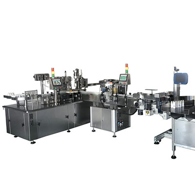
CNC Milling Boring Machine, GMC Series Gantry Type
Primary Parts of CNC Milling Boring Machine
1. Crossbeam
Crossbeam cast in resin-sand, steel insert guide ways hardened to HRC 6 0 / - 2, and ground. It features low coefficient of friction and large bearing capacity, making our CNC milling boring machine suitable for heavy cutting operations.
2. 5-face head
The spindle head integrates vertical and horizontal spindle orientation, and can be indexed in a rotary axis to increments of 5 degrees, and can also allow machining on 5 faces of the work-piece.
3. The beds, columns, crossbeams and rams of our CNC milling boring machine are all cast us ingressions and technology, with well-designed ribbing, producing a machine frame with high rigidity and excellent stability.
4. Horizontal-vertical conversion tool magazine
Automatic tool-changing system saves time with installing and clamping tools, thus improving the overall working efficiency of our CNC boring machine.
5. Bed
Bed section is cast using resin-sand technique, and is very sturdy and rigid in its construction. The bed can fully support the weight of the gantry to keep the milling boring machine perform stably.
6. Worktable
The X-axis double guideway is a type of western-made heavy-duty linear guideways which provide low friction, quick response, little vibration at high speed, and no shudder at low speed.
CNC Functions of Milling Boring Machine
Minimum pulse resolution on linear axes is 0.001 mm.
Compensation functions include reverse clearance compensation, compensation for over-quadrant error, tool-length and tool-radius compensation, and optional thermal compensation.
Feed functions include feed override adjustment, feed rate per minute, feed rate per revolution, and limit for programmable acceleration.
Spindle functions include spindle speed, spindle override adjustment, spindle orientation, and spindle speed limit.
Interpolation Types
Positioning, accurate stop, 3-coord in ATE linear interpolation, arc interpolation of any two coordinates, helical interpolation, feed pause, and thread cutting.
Edit Functions
Program segment index
Program number index
Background editing
Teach-in programming
Program protection
Safety Protective Function
Program testing, limiting of programmable machining area, software limitation monitor, hardware limitation monitor, E-stop, static monitor, speed monitor, position monitor, contour monitor.
CNC Programming
Fixed cycles of milling, drilling, and boring
Metric/inch programming
Absolute/incremental programming
Macro programming
Plane section
Workpiece coordinates
Operation Methods
Automatic, single-unit DNC, MDI, teach-in, incremental, dry run, single block
Display Contents
Current position, real cutting speed, program, operation error, alarm information, self-diagnosis functions
Data Transfer
Data I/O via USB interface
Data I/O via RS232C serial interface
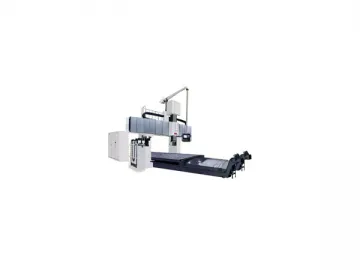
Main Technical Specifications of Gantry Type CNC Milling Boring Machine
| Item | Units | GMC1530r1 | GMC1530r2 | GMC2040r2 | ||
| Worktable | Worktable size | mm | 1500×3000 | 1500×3000 | 2000×4000 | |
| Width of gantry | mm | 2100 | 2100 | 2600 | ||
| Max. load capacity | kg | 10000 | 10000 | 20000 | ||
| T-slot | mm×n | 28×7 | 28×7 | 28×11 | ||
| Machining range | Worktable travel (X-axis) | mm | 3600 | 3600 | 4200 | |
| Saddle travel (Y-axis) | mm | 2700 | 2700 | 3200 | ||
| Spindle box travel (Z-axis) | mm | 800 | 1000(1250 Optional) | 1000(1250 Optional) | ||
| C-axis | 5°×72 | 5°×72 | 5°×72 | |||
| Distance from spindle nose to table surface | Max. | mm | 1000 | 1200 | 1200 | |
| Min. | mm | 200 | 200 | 200 | ||
| Spindle | Spindle taper (7:24) | ISO50 | ISO50 | ISO50 | ||
| Spindle speed range r/min | r/min | 10-3000 | 10-2000 | 10-2000 | ||
| Spindle torque | N.m | 1321/1821 | 1359/1873 | 1359/1873 | ||
| Spindle motor power | kW | 37/51 | 37/51 | 37/51 | ||
| Square ram section size | mm | 350×350 | 420×470 | 420×470 | ||
| Feed | Cutting feed speed range | mm/min | 1-5000 | 1-5000 | 1-5000 | |
| Rapid travel | X-axis | m/min | 13 | 13 | 13 | |
| Y-axis | m/min | 13 | 13 | 13 | ||
| Z-axis | m/min | 10 | 10 | 10 | ||
| Tool magazine | Capacity Pcs | 40, 60 | 40, 60 | 40, 60 | ||
| Tool selection method | Optional | Optional | Optional | |||
| Max. tool diameter | Full | mm | φ125 | φ125 | φ125 | |
| Adjacent socket empty | mm | φ250 | φ250 | φ250 | ||
| Max. tool length | mm | 400 | 400 | 400 | ||
| Max. tool weight | kg | 20 | 20 | 20 | ||
| Tool changing time | s | 5.5 | 5.5 | 5.5 | ||
| Positioning accuracy | GB/T19362.1-2003 Executing national standard | X-axis | mm | 0.03 (0.023 with sealed encoder) | 0.03 (0.023 with sealed encoder) | 0.032 (0.025 with sealed encoder) |
| Y-axis | mm | 0.03 (0.023 with sealed encoder) | 0.03 (0.023 with sealed encoder) | 0.032 (0.025 with sealed encoder) | ||
| Z-axis | mm | 0.025 | 0.025 (0.02 with sealed encoder) | 0.025 (0.02 with sealed encoder) | ||
| Repeatability | GB/T19362.1-2003 Executing national standard | X-axis | mm | 0.02 (0.016 with sealed encoder) | 0.02 (0.016 with sealed encoder) | 0.022 (0.016 with sealed encoder) |
| Y-axis | mm | 0.02 (0.016 with sealed encoder) | 0.02 (0.016 with sealed encoder) | 0.022 (0.016 with sealed encoder) | ||
| Z-axis | mm | 0.01 | 0.01 (0.008 with sealed encoder) | 0.01 (0.008 with sealed encoder) | ||
| Electrical total capacity KVA | 110 | 110 | 110 | |||
| CNC system | Siemens 840D | Siemens 840D | Siemens 840D | |||
Links:https://www.globefindpro.com/products/96310.html
-
 Flat Bed CNC Lathe, CAK50/61 Series
-
 HMC-c Horizontal Machining Center
-
 Slant Bed CNC Lathe, HTC63/80, HTC63b/80b
-
 Radial Drilling Machine
-
 Moving Gantry Turning Milling Center GTM500200
-
 HMC-e Horizontal Machining Center
-
 Slant Bed CNC Lathe, HTC32n
-
 Horizontal CNC Lathe ETC-h Series
-
 Conventional Lathe CA Series
-
 Slant Bed CNC Lathe, HTC16
-
 Slant Bed CNC Lathe, HTC32, HTC45, HTC54 Series
-
 Vertical Machining Center VMC2180S, VMC21100S, VMC2580S
