HMC-c Horizontal Machining Center
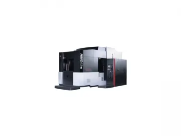
HMC-c series horizontal machining center adopts same structure with HMC-e, but increases the spindle speed up to 10000r/m and each axis travel speed to 40m/min. It is more suitable for applications in the industries of automobile, diesel engine, and home electric appliances, etc., for higher needs of production efficiency.
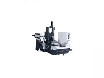
The direct drive spindle structure features low noise, small vibration and optimum finishing.
Linear encoder is standard accessory. The closed loop control makes horizontal machining center obtain high position accuracy.
The good chip removing system has structure of 2 helix chip conveyors on the 2 side of machining area, chain type chip conveyor in the middle and spraying system on the top of the protection cover washing away chips, which reduces thermal deformation and then improves the accuracy stability of the machine.
The tool magazine adopts cam indexing mechanism which has high indexing accuracy and fast tool changing speed.
The main components of our machining center are through finite element analysis and optimization.
Specifications of Horizontal Machining Center
| Model | Units | HMC50c | HMC63c | HMC80c | ||
| Worktable | Worktable size | mm | 500×500 | 630×630 | 800×800 | |
| Worktable load | kg | 500(uniformly distributed) | 1200(uniformly distributed) | 2000(uniformly distributed) | ||
| Width of T slot | mm | 18×5 | 18×7 | 18×7 | ||
| Number of worktable | 2(changing pallets) | 2(changing pallets) | 2(changing pallets) | |||
| Changing time | s | 12 | 15 | 20 | ||
| Machining range | Max. travel of column-X axis | mm | 800 | 1000 | 1350 | |
| Max. travel of headstock-Y axis | mm | 700 | 900 | 1100 | ||
| Max. travel of worktable-Z axis | mm | 800 | 900 | 1100 | ||
| Worktable rotation-B axis | 0.001° | 0.001° | 0.001° | |||
| Max. swing dia. of workpiece | mm | φ700 | φ1000 | φ1250 | ||
| Max. height of workpiece | mm | 800 | 1000 | 1200 | ||
| Distance between spindle end surface and worktable center | mm | 70-870 | 150-1050 | 150-1250 | ||
| Distance between spindle center and worktable surface | mm | 50-750 | 50-950 | 50-1150 | ||
| Spindle | Taper (7:24) | 7:24 NO.40 | 7:24 NO.50 | 7:24 NO.50 | ||
| Diameter of front bearing | mm | φ70 | φ100 | φ100 | ||
| Rotating speed range (stepless) | r/min | 10-10000 | 10-10000 | 10-10000 | ||
| Max. output torque | N.m | 95.4/117 | 140/165 | 140/165 | ||
| Spindle motor power | kW | 15/18.5(30 min) | 22/26(30 min) | 22/26(30 min) | ||
| Max. axial resisting force of spindle | N | 7000 | 10000 | 10000 | ||
| Feed | Feed speed range during machining X,Y,Z | mm/min | 1-40000 | 1-40000 | 1-40000 | |
| Rapid feed | X axis | m/min | 40 | 40 | 40 | |
| Y axis | m/min | 40 | 40 | 40 | ||
| Z axis | m/min | 40 | 40 | 40 | ||
| Tool magazine and automatic tool changing device | Tool magazine capacity | 40 | 40 | 40 | ||
| Tool selection method | Pcs | Supplied with machine | Supplied with machine | Supplied with machine | ||
| Max. tool weight | kg | 8 | 15 | 20 | ||
| Max. tool length | mm | 350 | 400 | 400 | ||
| Max. tool diameter | mm | φ75(when next pocket is emptyφ150) | φ125(when next pocket is emptyφ250) | φ125(when next pocket is emptyφ250) | ||
| Tool changing time | s | 4 | 4 | 4 | ||
| Tool shank specification | ISO7388/1-A JT40 | ISO7388/1-A JT50 | ISO7388/1-A JT50 | |||
| Pin model | ISO7388/2 LDA-40 | ISO7388/2 LDA-50 | ISO7388/2 LDA-50 | |||
| Positioning | X, Y, Z axes | mm | 0.008 | 0.01 | 0.012 | |
| accuracy of | ||||||
| machine | B axis | 10 | 10 | 10 | ||
| Repeatability | X, Y, Z axes | mm | 0.005 | 0.006 | 0.008 | |
| positioning | ||||||
| accuracy | B axis | 6 | 6 | 6 | ||
| System | CNC system | FANUC 18i | FANUC 18i | FANUC 18i | ||
Links:https://www.globefindpro.com/products/96312.html
-
 Slant Bed CNC Lathe, HTC63/80, HTC63b/80b
-
 Radial Drilling Machine
-
 Moving Gantry Turning Milling Center GTM500200
-
 HMC-e Horizontal Machining Center
-
 CNC Pipe Threading Lathe STC1135pipe, STC1835pipe
-
 Vertical Machining Center, VMC1600B, VMC2100B
-
 Flat Bed CNC Lathe, CAK50/61 Series
-
 CNC Milling Boring Machine, GMC Series Gantry Type
-
 Slant Bed CNC Lathe, HTC32n
-
 Horizontal CNC Lathe ETC-h Series
-
 Conventional Lathe CA Series
-
 Slant Bed CNC Lathe, HTC16
