Coating Wire Wound Resistor
Coating wire wound resistor is composed of circular ceramic resistor,with heat resisting material coated wound wire. Thus it is widely used inautomotive electronics, household appliances, communication equipment, energy-savinglamps, automatic control device (like converter) and other industries.
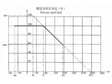
Performance Of Coating Wire Wound Resister
| Item | Test Method | Requirement | |
| Resistance Series, Tolerance | E24; ±5% ±10% | ||
| Solder Ability | 265±5℃, 2s+0.5s, Immersion height:1.5~2.0mm | 265±5℃; 2s+0.5s; 1.5-2.0mm | △R≤± (1%R+0.05Ω) No visible damage; Surface without solder>95% |
| Terminal Strength | 10N: 30±1.5s | 10N 30±1.5s | △R≤±(1%R+0.05Ω) No visible damage |
| Short Time Overload | 10x Rated power: 5s | 10x Rated power 5s | △R≤±(1%R+0.05Ω) |
| Resistance to Soldering Heat | 350℃±10℃; Immersion height:3~3.5mm | 350℃±10℃ 3-3.5mm | △R≤± (1%R+0.05Ω) No visible damage |
| Vibration | Min. (10-500Hz and 0.75mm, or 98m/s2 ) Direction: x、y and z, totally 6h | Min. (10-500Hz and 0.75mm, or 98m/s2 ) Direction: x、y and z, totally 6h | △R≤±(1%R+0.05Ω) No visible damage |
| Load Life Under Room Temperature | 1.5h-on and 0.5h-off : 1000h | 1.5h-on and 0.5h-off : 1000h | △R≤±(5%R+0.1Ω) |
| Moisture Resistance | 40℃; RH=90~95%: 96h | 40℃; RH: 90-95% ; 96h | △R≤±(5%R+0.1Ω) |
Derating Curve
Optional Models
RX27-4HS / RX27-4HV
| Type | Rated Power (W) | Resistance Range( Ω) | Dimensions (mm) | ||
| L | D | D | |||
| RX21-0.5 | 0.5 | 0.10-560 | 10±1 | 3.5±0.5 | 0.6 |
| RX21-(1) | (1) | 0.1-1k | 14 ±1 | 33 ±0.5 | 0.8 |
| RX21-2 | 2 | 0.15-5.1k | 16±1 | 6±1 | 0.8 |
| RX21-4 | 4 | 0.15-10k | 26 ±2 | 9±1 | 0.8 |
| RX21-8 | 8 | 0.15-33k | 3412 | 10 ±1 | 1 |
| RX2-(12) | (12) | 1-33k | 46 ±2 | 10 ±1 | 1 |
| RX2t-(15) | (15) | 1»39k | 52 ±2 | 10±1 | 1 |
Nominal Resistance Allowable Deviation: ±2%(G);±5%(J); ±10%(K)
The power in brackets belongs to a non-standard power series.
RX25 Coating Wire Wound Resistor
| Type | Rated Power (W) | Resistance Range (Ω) | Dimensions (mm) | |||
| L | D | I | T | |||
| RX25-3 | 3 | 0.1-2k | 19±1 | 6±1 | 12±1 | 0.5 |
| RX25-5 | 5(6) | 0.1-5k | 24±1 | 9±1 | 6±1 | 0.5 |
Resistance Tolerance: ±5%; ±10%
RX26 Coating Wire Wound Resistor
| Type | Rated Power (W) | Resistance Range (Ω) | Dimensions (mm) | ||||||
| L | D | H | B | D | D1 | T | |||
| RX26-30 RX26-80 | 30 | 0.1-1k | 80±1.5 | 17±2 | 36±2.5 | 35 ±0.8 | 8±0.5 | 2 | 5.4 |
| 80 | 0.1-1.5k | 91 ±2.4 | 29±3 | 46±3 | 4.5±1 | 20±1.1 | 2.5 | 8 | |
| RX26-100 | 100 | 0.5-2k | 140 ±3.2 | 29±3 | 46±3 | 4.5±1 | 20±1.1 | 2.5 | 8 |
| RX26-120 | 120 | 0.5-2.2k | 160 ±3.5 | 29±3 | 46±3 | 4.5 ±1 | 20±1.1 | 2.5 | 8 |
| RX26-150 | 150 | 0.5-4.3k | 195 ±3.5 | 29±3 | 46±3 | 4.5±1 | 18±1.1 | 2.5 | 8 |
| RX26-200 | 200 | 1-4.7k | 215 ±6 | 29±3 | 46±3 | 4.5±1 | 18±1.1 | 2.5 | 8 |
| RX26-2S0 | 250 | 1-6.1k | 303 ±6 | 29±3 | 46±3 | 4.5±1 | 18±1.1 | 2.5 | 8 |
| RX26-300 | 300 | 1.5-6.3k | 254±6 | 45±4 | 63±4 | 6±1 | 24 ±1.2 | 4.5 | 8 |
| RX26-400 | 400 | 1.5-6.8k | 330 ±6 | 45±4 | 63±4 | 6±1 | 24 ±1.2 | 4.5 | 8 |
| RX26-500 | 500 | 1.5-8.2k | 303 ±6 | 55±4 | 73±4 | 6±1 | 35±3 | 4.5 | 10 |
| RX26-600 | 600 | 1.5-9k | 300 ±6 | 60±4 | 73±4 | 6±1 | 35±3 | 4.5 | 10 |
| RX26-750 | 750 | 2-10k | 390 ±6 | 60±4 | 73±4 | 7±1 | 35±3 | 4.5 | 12 |
| RX26-1000 | 1000 | 5-12k | 500 ±6 | 70±4 | 80±4 | 7±1 | 40±5 | 5 | 12 |
Note: coating wire wound resistor with corrugated ribbon can bemanufactured with a smaller size.
RXT Flat Type Coating Wire Wound Resistor
Nominal resistance allowable deviation: ±5% (J) ±10% ( K)
Nominal resistance series: the priorities are the E12 and E24 series of IEC63.
Various types of pin modes, resistance wire corrugated structure and multi-pin resistor are available based on clients’requirements.
| Type | Rated Power (W) | Resistance Range (Ω) | Dimensions (mm) | |||||||||||
| L1 | L2 | L3 | L4 | L5 | H | H1 | H3 | B | D | D1 | t | |||
| RXT-20 | 30 | 0.1-1k | 60±2 | 49±2 | 12±1 | 5 | 5 | 40±1 | 22±1 | 16±1 | 22±1 | 8 | 3 | 1.2 |
| RXT-100 | 100 | 0.1-1.5k | 100±2 | 86±2 | 14 ±1 | 6 | 6 | 40±1 | 24±1 | 16±1 | 22±1 | 8 | 3.5 | 1.2 |
| RXT-300 | 300 | 0.5-3.6k | 300 ±2 | 280 ±2 | 16±1 | 10 | 10 | 56±1 | 36±1 | 18±1 | 28±1 | 18 | M3 | 2 |
Links:https://globefindpro.com/products/24150.html
-
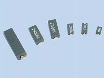 SMD Resistor, Surface Mount Resistor
-
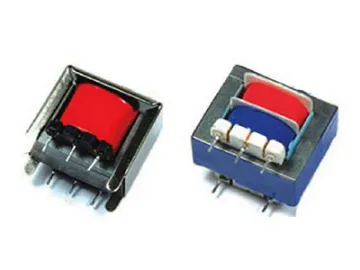 PCB Transformer (EI Core)
-
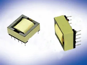 Switch Mode Transformer (EFD, EPC Core)
-
 Strut Channel and Electrical Support
-
 SMD Power Inductor, CDRH2B/3B/4B Series
-
 Milliohm Resistor
-
 Switch Mode Power Transformer (RM, POT Core)
-
 Diode
Diode
-
 SMD10.5mm Power Inductor
-
 Push Pull Transformer, Low Frequency Transformer
-
 Aluminum Housed Chassis Mounted Wire Wound Resistor
-
 SMD12.3mm Power Inductor
