Integrated Sludge Drying and Incineration System
Process Flow of Sludge Treatment System
The main process flow for sludge treatment adopts the "drying incineration flue gas treatment" process.
Sub-systems
The process systems include: sludge collection and transportation system, sludge drying system, sludge incineration system, surplus heat utilization system, flue gas purification system, etc.
An enclosed sludge receiving workshop is set up within the plant area. Depending on the incoming moisture content, 80% and 60% moisture content sludge collection and transportation systems are in place, along with a deodorization system. During unloading, 60% moisture content sludge is temporarily stored in a feed pit and conveyed to the drying system by equipment including bridge grab, sludge receiving bin, and scraper conveyor. Sludge with 60% moisture content requires a buffer bin with a slide rack for uniform feeding. Sludge with 80% moisture content is first pumped to a wet sludge storage bin for temporary storage after passing through a wet sludge receiving bin and then pumped to the drying system for disposal. Wet sludge can also be conveyed from the storage bin to the sludge filter press system; after mechanical dewatering, it is sent to the 60% moisture content collection area.
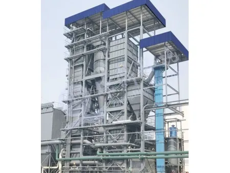
Upon entering the drying machine, the sludge is dispersed throughout the drying bed material layer by a dispersing device located beneath the inlet. The drying machine features a dual heating system consisting of high-temperature inert flue gas and steam coils. Sludge is dried to an appropriate moisture content through convective heat exchange with the flue gas and grinding with the bed material.
After heat exchange, the flue gas is discharged from the top of the drying machine and enters a cyclone dust collector. The collected dust is transported by a screw conveyor into a scraper conveyor and then mixed with the dried sludge to be incinerated in the furnace.
The wet flue gas, after dust removal, enters a flue gas condenser, where condensation removes the water content from the gas. The resulting wastewater flows from the bottom of the condenser into a wastewater collection pool and is then pumped to a wastewater treatment system. Some clarified water from the collection pool is circulated by a pump to rinse the heat exchange pipes inside the condenser, ensuring long-term heat exchange efficiency. The dehydrated organic flue gas is sent to the incinerator for re-incineration by a drying induced draft fan, effectively solving odor emission issues.
The dried sludge overflows from the side of the fluidized bed and is transported by a screw conveyor and a Z-shaped scraper conveyor to a dry sludge buffer silo in front of the furnace.
The buffer silo is equipped with a crushing device to prevent sludge from re-moistening and agglomerating. The sludge is then transported by an air-cooled screw conveyor into the incinerator for incineration. A calcium carbonate dosing system is equipped at the front of the furnace, at the rear end of the inlet screw, calcium carbonate is introduced by a feeder, which is then thoroughly mixed with the sludge. The mixture is then sent to the furnace for incineration, achieving in-furnace desulfurization.
Incinerator and Boiler System Process FlowA primary air fan extracts air from the discharge room and sends it to a waste heat recovery system. The air is heated in a preheater and then sent to the bottom of the incinerator's air chamber. The air is blown into the incinerator through air caps on the distribution plate, creating a fluidized effect in the bed material. A secondary air fan supplements air at the top of the bed material to ensure complete incineration of the sludge.
The incinerator features a well-insulated furnace design, allowing the sludge's self-sustain combustion at calorific value ~1,000 kcal. The furnace's combustion temperature 850℃~900℃, meeting municipal solid waste incineration standards by government. The tall furnace design ensures that flue gas remains inside for at least 2s, allowing complete organic matter decomposition at high temperature before exiting through the top of the incinerator. An SNCR denitrification device is installed at the furnace outlet, by which NOx components are removed via injecting urea solution to the flue gas. Furnace slag is discharged through a pipe at the bottom of the incinerator into a rotary cooler, where the high-temperature slag is cooled to below 100℃ before being temporarily stored in a slag bin. The slag can be recycled for brick-making or cement production.
The high-temperature flue gas enters a waste heat boiler, generating steam from the recovered heat. Part of the steam is used for fluidized bed drying, while the remaining steam can be utilized for other purposes according to customer’s needs.
The flue gas undergoes multi-stage heat recovery in the system, stages include air preheater, flue gas reheater, evaporator, economizer, etc., while position for SCR device installation is available.
Flue Gas Treatment System Process FlowThe final flue gas is discharged at a temperature below 200°C. The flue gas enters the dry reaction tower, where hydrated lime is injected, reacting with the acidic substances in the flue gas through acid-base neutralization. The deacidified flue gas (with dust) exits the dry reaction tower through the side and enters the baghouse dust collector.
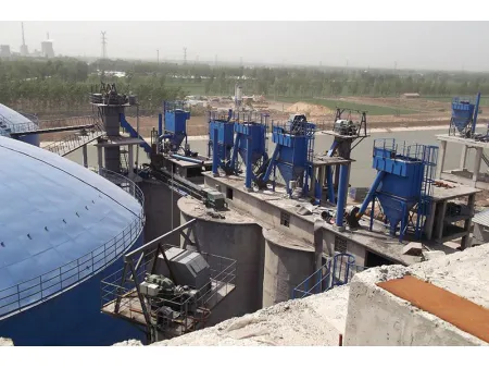
The baghouse dust collector consists of two stages. Stage I removes 99% of the suspended particles from the flue gas, the removed dust is typically identified as general solid waste. The dust is temporarily transported to and stored in an ash silo via a pneumatic conveying system and can be utilized for brick making, cement production, etc.
In Stage II, activated carbon is injected into the inlet flue, adsorbing small amounts of heavy metals and dioxins in the flue gas. Stage II aims to remove extremely small amounts of suspended particles. The fly ash is typically identified as hazardous waste, which is temporarily stored in a hazardous waste ash silo and centrally disposed of.
The flue gas at the outlet of Stage II baghouse is sent to the wet desulfurization tower by an induced draft fan. Through a pH control system, a desulfurization agent is added to the tower for circulating spray, achieving final desulfurization. The purified flue gas is discharged in compliance with emission standards through an integrated chimney at the top of the desulfurization tower. The salt-containing wastewater generated after desulfurization is pumped to the wastewater treatment system by a sewage pump.
Before entering the Stage II baghouse, a portion of the flue gas is drawn off and sent to the waste heat recovery system by a booster fan. The flue gas is reheated in the recovery system's flue gas reheater and then sent to the drying system as fluidizing air for the dryer. In this way, a large circulation of drying flue gas is formed within this system, fully utilizing the internal waste heat, ensuring high recovery rate and low energy consumption.
Links:https://globefindpro.com/products/354.html
-
 Top Hammer Coupling Sleeves
-
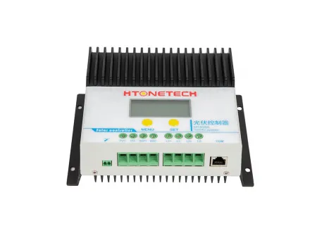 48V Solar Charge Controller (80A-150A)
-
 7" Inch Double-sided LCD Intelligent Conference Electronic Table Name Card
-
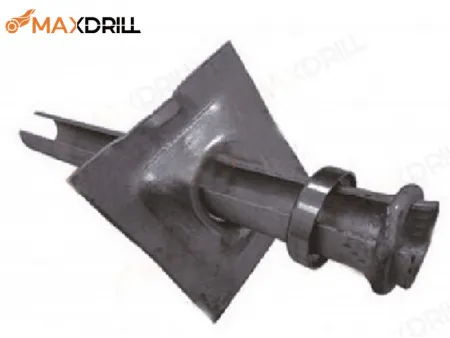 Friction Bolts
-
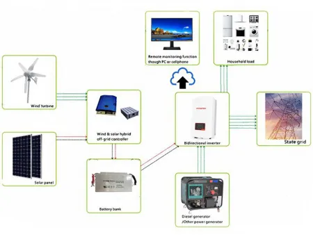 Hybrid Solar-Wind-Diesel Power Generation System
-
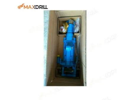 YT27 Air Leg Rock Drill
-
 Baghouse Dust Collector
-
 LMT5310TXF Micro-Surfacing Paver
-
 LMT5160TFCT Mini Chip Sealing Distributors and Equipment
-
 LMT5312TFC Asphalt Synchronous Chip Sealing Distributors and Equipment
-
 PVC Automotive Wire Harness Tape
-
 Solar Cable
