Methods to Inspect the Cast iron Straight Edge
Ⅰ. Straightness Inspection of the Working Surface
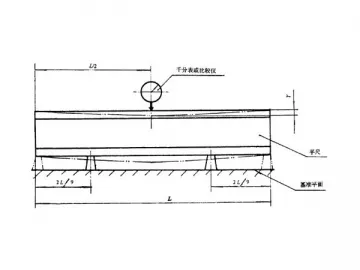
Use the block to support the I-shaped cast iron straight edge. Choose the proper bridge plate according to the length of the working surface of the cast iron straight edge. Then, place the bridge plate on one end of the straight edge, and fix the reflector or gradienter onto the plate. According to the span, gradually move the bridge plate from one end to the other end of the straight edge. Every time after you have moved the plate a span, you should get the reading from the autocollimator with the division value of 1″, or from the electronic level meter whose division value is of 0.001mm/m. The difference between the maximum and minimum values is the working surface straightness error of the cast iron straight edge.
Here below is the outline drawing of the inspection Method.
Ⅱ. Contact Area Detection of the Cast Iron Straight Edge
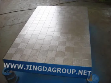
Apply the developer onto the working surface of the cast iron straight edge that needs testing. Then lap the straight edge onto the higher precision cast iron surface plate or cast iron straight edge. The obvious contact points will appear on the tested cast iron straight edge. After that, place a 50mm×25m transparent thin plate such as organic glass plate onto any position of the tested straight edge. You ought to choose the transparent thin plate which has been drawn with 200 small squares. Finally, you can observe the contact points contained within each square, and calculate their coverage proportion. Divide the total coverage proportion by 2, and then the value you get is coverage ratio of the contact points in the inspected area.
Ⅲ. Inspect the Verticality between the Side Surface and Working Surface
Place the cast iron straight edge onto the cast iron surface plate. Make the gauge stand which is equipped with the dial indicator, to pass through the standard round bar. And it should direct to the zero point of the standard square. Then, make the gauge stand contact tightly with one side surface of the cast iron straight edge. The reading you get from the dial indicator is the verticality of the side surface. Inspect verticality of the other side surface in the same manner.
Ⅳ. Depth of Parallelism between the Working Surfaces
Use the cast irons surface plate as the basal plane, and place it onto the precision cast iron surface plate. Later, use the dial indicator to measure the heights of at least three places of the working surface.
When there is no applicable cast iron surface plate, you can use the supporting surface. Under such case, you need to use the lever micrometer or dial indicator which comes with the division value of 0.002mm.
Ⅴ. Inspect the Natural Deflection of the Cast Iron Straight Edge
Use the block to the support the I-shaped cast iron straight edge to the standard position, and the straight edge should be placed onto the basal plane. The indicator with the division value of 0.001mm should be used. After you get the measurement reading at the middle part of the working surface, you need to move the block to the maximum bearing supporting distance. 10 minutes later, get the reading from the dial indicator. The difference between the two readings is the natural deflection of the cast iron straight edge.
Links:https://globefindpro.com/products/39385.html
-
 Cast Iron Coordinate Lineation Surface Plate
-
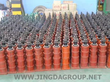 Surface Plate Leveling Bolt
-
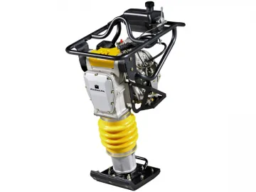 MR85D Tamping Rammer
-
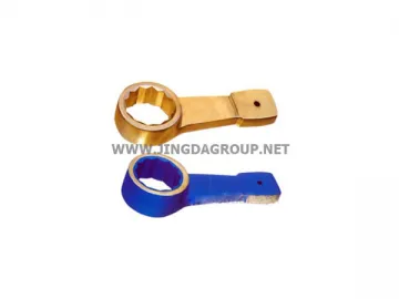 Non-sparking Striking Box End Wrench
-
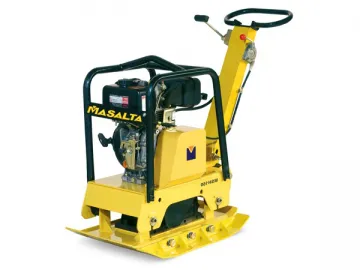 MSH160 Mechanical Reversible Compactor
-
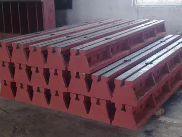 Cast Iron Rails
-
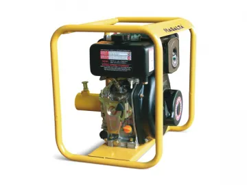 MVDS Concrete Vibrator
-
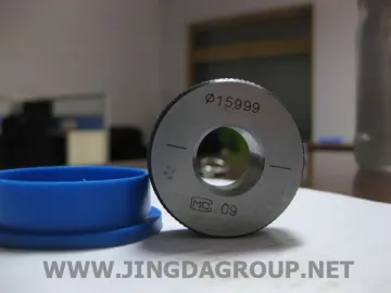 Master Ring Gauge
-
 MS50 Forward Compactor
-
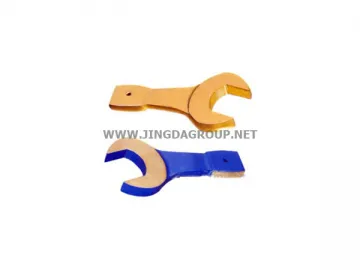 Non-sparking Striking Open End Wrench
-
 Non-sparking Bent Striking Box End Wrench
-
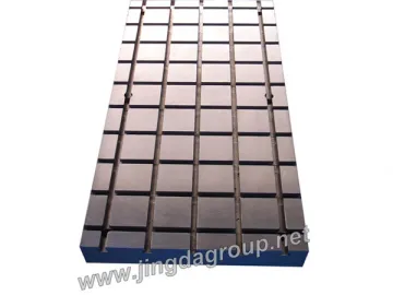 Cast Iron T Slotted Surface Plate