Roller Linear Guide
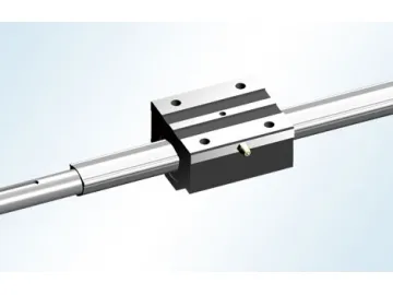
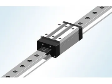
Made of bearing steel, GZB roller linear guide is composed of rail, slide block, rollers, reverse unit, retainer, roller cage, and seal gasket, etc. The roller linear guide has high rigidity rollers and its load bearing pattern is changed from the traditional point contact to line contact. The roller linear guide can withstand a large torque due to its inner V type groove design. In addition, the structure of slide block is optimized by finite element analysis. All of this contributes to the high load carrying capacity of our roller linear guide. Moreover, the contact angle between the roller and raceway is 45º, enabling the roller linear guide to have equal load in four directions.
Roller cage is set among rollers to keep them apart and avoid collision, eliminating any noise caused by roller collision. It also makes the rollers move straight and stably. There is an oil layer between roller and the cage which greatly reduces friction and reduces heat generated by the linear guide during moving, ensuring high speed and high accuracy motion. What's more, with lubricating grease stored in the cage, the roller linear guide is free from maintenance for a long period of time and the operating life is extended. These are a few reasons why our roller linear guide is widely used for machining centers, NC lathes, grinders, etc.
Technical Specifications Seal Type and Dimension Increase| Seal code | Seal type | Amounting Dimension L1 Increase(mm) | |||||||
| GZB25 | GZB35 | GZB45 | GZB55 | GZB65 | GZB85 | GZB100 | GZB125 | ||
| MM | End seal | +0 | +0 | +0 | +0 | +0 | +0 | +0 | +0 |
| MN | End seal+side seal | +0 | +0 | +0 | +0 | +0 | +0 | +0 | +0 |
| MX | End seal+side seal + scraper | +1.5 | +1.5 | +2 | +2.5 | +3 | +4 | +5 | +6 |
| MY | Tighten-end seal+side seal | +2 | +2 | +2.5 | +2.5 | +3 | +4 | +5 | +6 |
| MZ | Tighten-end seal+scraper | +3 | +3.5 | +4.5 | +5 | +6 | +8 | +10 | +12 |
GZB ① 35 ② A ③ A ④ L ⑤ T ⑥ MM ⑦ 2 ⑧ P1 ⑨
2 ⑩ 7000 ⑪ (2)
⑫ -4
⑬ ①Type code of four direction equal load ball guide
②Nominal dimension of rail
③Code of block width (A for wide (flange) type, B for narrow type)
④Mounting hole of block (A for thread hole, B for through hole) ⑤Code of block length (standard is not specified, L for lengthen)
⑥Code of special requested block (standard is not specified)
⑦Seal type
⑧Number of blocks used per rail ⑨Preload, total P0, P1, P, P3
⑩Number of rails used in the same surface ⑪ Rail length
⑫ Number of joint guide (non joint is not specified)
⑬ Accuracy grade, total 1, 2, 3, 4, 5, 6 grades
| Type | Dimension of assembly | Dimension of block | Dimension of rail | ||||||||||||||
| H | W | B1 | B3 | K | T | T1 | M | Ф | L0 | L1 | L2 | L3 | L4 | B2 | H1 | d × D × h | |
| GZB25AA GZB25AAL | 36 | 23.5 | 70 | 57 | 31.5 | 9.5 | 10 | 8 | 6.8 | 10 | 100 120 | 66 86 | 45 | 40 | 23 | 24 | 7 ×11×9 |
| GZB35AA GZB35AAL | 48 | 33 | 100 | 82 | 42 | 13 | 21 | 10 | 8.5 | 12 | 128 147 | 86 105 | 62 | 52 | 34 | 30.5 | 9 ×14×12 |
| GZB45AA GZB45AAL | 60 | 37.5 | 120 | 100 | 51 | 15 | 25 | 12 | 10.5 | 15 | 154 182 | 102 130 | 80 | 60 | 45 | 38 | 14 ×20×16 |
| GZB55AA GZB55AAL | 70 | 43.5 | 140 | 116 | 60 | 20 | 29 | 14 | 12.5 | 18 | 172 210 | 118 156 | 95 | 70 | 53 | 44 | 16 ×23×20 |
| GZB65AA GZB65AAL | 90 | 53.5 | 170 | 142 | 76 | 25 | 37 | 16 | 14.5 | 23 | 210 270 | 147 207 | 110 | 82 | 63 | 55 | 18 ×26×22 |
| GZB85AAL | 110 | 65 | 215 | 185 | 95 | 24 | 44 | 20 | 17.5 | 26 | 350 | 254 | 140 | 140 | 85 | 73 | 24 ×35×28 |
| GZB100AAL | 120 | 75 | 250 | 220 | 105 | 25 | 51.5 | 20 | 17.5 | 30 | 395 | 286 | 200 | 200 | 100 | 80 | 26 ×39×32 |
| GZB125AAL | 160 | 97.5 | 320 | 270 | 135.5 | 30 | 65 | 24 | 21 | 45 | 491 | 360 | 205 | 205 | 125 | 115 | 33 ×48×45 |
| Dimensions of Oil Cup | Dynamic Load Rating | Static Load Rating | Torque Rating | Weight of Block | Weight of Rail | ||||||
| F | Max. single length | G | P | N | C(KN) | CO(KN) | MA(Nm) | MB(Nm) | MC(Nm) | Kg | Kg/m |
| 30 | 6000 | M6 | 12 | 5.5 | 26.5 33.8 | 50.8 71.6 | 570 830 | 570 830 | 710 980 | 0.6 0.8 | 3.2 |
| 40 | 6000 | M6 | 13 | 8.5 | 50.5 61 | 121 162 | 1548 2708 | 1548 2708 | 2343 3283 | 1.6 2.0 | 5.9 |
| 52.5 | 6000 | M8 ×1 | 14 | 11 | 84.5 99.6 | 191 236 | 3156 5560 | 3156 5560 | 4858 6736 | 2.5 3.5 | 9.8 |
| 60 | 6000 | M8 ×1 | 14 | 13 | 123 154 | 292 390 | 5267 9713 | 5267 9713 | 8243 11927 | 4.3 5.9 | 13.3 |
| 75 | 6000 | M8 ×1 | 14 | 17 | 192 248 | 451 613 | 10823 20808 | 10823 20808 | 17762 22957 | 8.6 12.3 | 20.3 |
| 90 | 6000 | M8 ×1 | 14 | 21 | 460 | 1050 | 45600 | 45600 | 51420 | 21.6 | 35.2 |
| 105 | 6000 | M10 ×1 | 16 | 23 | 547 | 1330 | 61200 | 61200 | 73140 | 31.5 | 46.8 |
| 120 | 6000 | M10 ×1 | 16 | 23 | 1040 | 1924 | 123176 | 123176 | 114438 | 65.5 | 84.6 |
| Model | Dimensions of Assembly | Dimensions of Block | Dimensions of Rail | ||||||||||
| H | W | B1 | B3 | K | T | M × L0 | L1 | L2 | L3 | B2 | H1 | d × D × h | |
| GZB25BA GZB25BAL | 40 | 12.5 | 48 | 35 | 35.5 | 9.5 | M6 × 8 | 100 120 | 66 86 | 35 50 | 23 | 24 | 7 ×11×9 |
| GZB35BA GZB35BAL | 55 | 18 | 70 | 50 | 49 | 10 | M8 × 12 | 128 147 | 86 105 | 50 72 | 34 | 30.5 | 9 ×14×12 |
| GZB45BA GZB45BAL | 70 | 20.5 | 86 | 60 | 61 | 15 | M10 × 16 | 154 182 | 102 130 | 60 80 | 45 | 38 | 14 ×20×16 |
| GZB55BA GZB55BAL | 80 | 23.5 | 100 | 75 | 70 | 18 | M12 ×1 8 | 172 210 | 118 156 | 75 95 | 53 | 44 | 16 ×23×20 |
| GZB65BA GZB65BAL | 90 | 31.5 | 126 | 76 | 76 | 23 | M16 × 16 | 210 270 | 147 207 | 70 120 | 63 | 55 | 18 ×26×22 |
| GZB85BAL | 110 | 35.5 | 156 | 100 | 95 | 30 | M18 × 25 | 350 | 254 | 140 | 85 | 73 | 24 ×35×28 |
| GZB100BAL | 120 | 50 | 200 | 130 | 105 | 33 | M20 × 27 | 395 | 286 | 200 | 100 | 80 | 26 ×39×32 |
| GZB125BAL | 160 | 57.5 | 240 | 184 | 135.5 | 40 | M24 × 30 | 491 | 360 | 205 | 125 | 115 | 33 ×48×45 |
| Dimensions of Oil Cup | Dynamic Load Rating | Static Load Rating | Torque Rating | Block Weight | Rail Weight | ||||||
| F | Max. single length | G | P | N | C(KN) | CO(KN) | MA(Nm ) | MB(Nm ) | MC(Nm ) | kg | Kg/m |
| 30 | 6000 | M6 | 12 | 9.5 | 26.5 33.8 | 50.8 71.6 | 570 830 | 570 830 | 710 980 | 0.5 0.7 | 3.2 |
| 40 | 6000 | M6 | 13 | 15.5 | 50.5 61 | 121 162 | 1548 2708 | 1548 2708 | 2343 3283 | 1.4 1.7 | 5.9 |
| 52.5 | 6000 | M8 ×1 | 14 | 21 | 84.5 99.6 | 191 236 | 3156 5560 | 3156 5560 | 4858 6736 | 2.48 3.2 | 9.8 |
| 60 | 6000 | M8 ×1 | 14 | 23 | 123 154 | 292 390 | 5267 9713 | 5267 9713 | 8243 11927 | 3.8 5.1 | 13.3 |
| 75 | 6000 | M8 ×1 | 14 | 17 | 192 248 | 451 613 | 10823 20808 | 10823 20808 | 17762 22957 | 6.3 8.9 | 20.3 |
| 90 | 6000 | M8 ×1 | 14 | 21 | 460 | 1050 | 45600 | 45600 | 51420 | 14.7 | 35.2 |
| 105 | 6000 | M10 ×1 | 16 | 23 | 547 | 1330 | 61200 | 61200 | 73140 | 24.5 | 46.8 |
| 120 | 6000 | M10 ×1 | 16 | 23 | 1040 | 1924 | 123176 | 123176 | 114438 | 46 | 84.6 |
As a specialized roller linear guide manufacturer and supplier based in China, we also provide radial linear guideway, convex linear motion spline, CNC cast iron worktable, mini ball screw, and much more.
Links:https://globefindpro.com/products/50203.html
