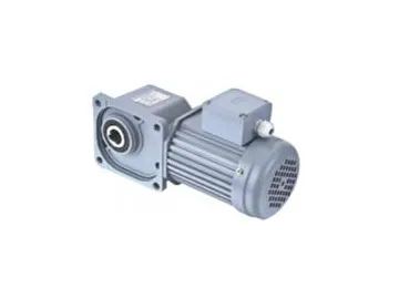
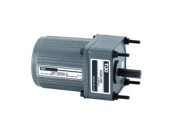
SZG-F Medium Right Angle Gear Motor
Used for transmission of automatic or semi-automatic equipment like conveyors, hoisting equipment, printing machines, packing equipment, food production machinery and many other associated devices.
Precautions for Use
1. High efficiency and low noise: these gear motors feature a hyperboloid gear design for because of the low noise output of helical gears and their high efficiency bevel gears. Compared to worm gearboxes, the sliding friction of hyperboloid gears is very small. Transmission efficiency can reach as high as 95%. Hyperboloid gears have a mesh of 2.5 gears.
2. Long life-time: Gears are made from high strength steel alloy with a carbonization coating treatment.
3. Much more convenient installation and operation: The mounting face of the motor is square and the four mounting bolt holes are distributed in a square shape as well. This allows for installation and maintenance convenience.
4. Integrated box design with a compact structure for space savings.
5. Cast Aluminum box, good heat dissipation: Compared with the cast iron box, cast aluminum box has better radiating effects without a need for a cooling fan.
6. Grease lubrication, no need for additional maintenance.
7. Compatibility with a variety of different gearboxes and motors: Matches with single phase motors, frequency-conversion motors, and brake motors, motor with encoder etc.
Technical Parameters
SZG-22-F Motor Parameter
| Frame Number | Type | Power (KW) | Voltage (V) | Frequency (Hz) | Rated Current(A) | Rated Speed (rpm) | Capacitor (μF) | Insulation Class | Protective System |
| 22 (Solid Output Shaft-22) (Hollow Output Shaft-16) | 1 Phase | 0.2 | 220 | 50 | 1.3 | 1420 | 12 | B | IP44 |
| 3 Phase | 0.2 | 220 | 50 | 0.92 | 1380 | / | |||
| 380 | 50 | 0.54 | 1390 | / | |||||
| 0.4 | 220 | 50 | 1.8 | 1350 | / | ||||
| 380 | 50 | 1.1 | 1370 | / |
| Frame Number | Ratio | Output Speed | Allowance Output Torque | Output AllowableO.H.L | Remark | ||||
| 50Hz | 0.2KW | 0.4KW | frame 22 | ||||||
| N.m | kgf.m | N.m | kgf.m | N | Kgf | ||||
| 22 (Solid Output Shaft-10) | 1/5 | 300 | 5.5 | 0.56 | 11 | 1.1 | 882 | 90 | |
| 1/10 | 150 | 11 | 1.1 | 23 | 2.3 | 1180 | 120 | ||
| 1/15 | 100 | 17 | 1.7 | 33 | 3.4 | 1370 | 140 | ||
| 1/20 | 75 | 23 | 2.3 | 44 | 4.5 | 1470 | 150 | ||
| 1/25 | 60 | 27 | 2.8 | 55 | 5.6 | 1670 | 170 | ||
| 1/30 | 50 | 33 | 3.4 | 67 | 6.8 | 1760 | 180 | ||
| 1/40 | 37.5 | 44 | 4.5 | 88 | 9 | 1860 | 190 | ||
| 1/50 | 30 | 55 | 5.6 | 111 | 11.3 | 1960 | 200 | ||
| 1/60 | 25 | 67 | 6.8 | 133 | 13.6 | 2160 | 220 | ||
| 1/80 | 18.8 | 84 | 8.8 | 169 | 17.2 | 2450 | 250 | ||
| 1/100 | 15 | 105 | 10.7 | 211 | 21.5 | 2450 | 250 | ||
| 1/120 | 12.5 | 126 | 12.9 | 253 | 25.8 | 2450 | 250 | ||
| 1/160 | 9.4 | 169 | 17.2 | 2450 | 250 | ||||
| 1/200 | 7.5 | 184 | 18.8 | 2450 | 250 | ||||
| 1/240 | 6.3 | 213 | 21.7 | 2450 | 250 | ||||
Note:
1. If sprocket, conveyor belt and gear are used when connect reducer shaft with machinery, output allowable O.H.L should be taken into consideration
2. O.H.L value is for reducer that the load act on the center.
| Frame Number | Type | Power (KW) | Voltage (V) | Frequency (Hz) | Rated Current(A) | Rated Speed (rpm) | Capacitor (μF) | Insulation Class | Protective System |
| 25 (Solid Output Shaft-25) (Hollow Output Shaft-25) | 3 Phase | 0.2 | 220 | 50 | 0.92 | 1380 | / | B | IP44 |
| 380 | 50 | 0.54 | 1390 | / | |||||
| 0.4 | 220 | 50 | 1.8 | 1350 | / | ||||
| 380 | 50 | 1.1 | 1370 | / |
| Frame Number | Ratio | Output Speed | Allowance Output Torque | Output AllowableO.H.L | Remark | ||||
| 50Hz | 0.2KW | 0.4KW | frame 25 | ||||||
| N.m | kgf.m | N.m | kgf.m | N | Kgf | ||||
| 25 (Solid Output Shaft-28) (Hollow Output Shaft-25) | 1/5 | 300 | 5.5 | 0.56 | 11 | 1.1 | 1002 | 102 | |
| 1/10 | 150 | 11 | 1.1 | 23 | 2.3 | 1200 | 122 | ||
| 1/15 | 100 | 17 | 1.7 | 33 | 3.4 | 1390 | 141 | ||
| 1/20 | 75 | 23 | 2.3 | 44 | 4.5 | 1490 | 152 | ||
| 1/25 | 60 | 27 | 2.8 | 55 | 5.6 | 1690 | 172 | ||
| 1/30 | 50 | 33 | 3.4 | 67 | 6.8 | 1780 | 181 | ||
| 1/40 | 37.5 | 44 | 4.5 | 88 | 9 | 1880 | 191 | ||
| 1/50 | 30 | 55 | 5.6 | 111 | 11.3 | 1980 | 202 | ||
| 1/60 | 25 | 67 | 6.8 | 133 | 13.6 | 2180 | 222 | ||
| 1/80 | 18.8 | 84 | 8.6 | 169 | 17.2 | 2470 | 252 | ||
| 1/100 | 15 | 105 | 10.7 | 211 | 21.5 | 2470 | 252 | ||
| 1/120 | 12.5 | 128 | 12.9 | 253 | 25.6 | 2470 | 252 | ||
| 1/160 | 9.4 | 169 | 17.2 | 2470 | 252 | ||||
| 1/200 | 7.5 | 184 | 18.8 | 2470 | 252 | ||||
| 1/240 | 6.3 | 213 | 21.7 | 2470 | 252 | ||||
Note:
1. If sprocket, conveyor belt and gear are used when connect reducer shaft with machinery, output allowable O.H.L should be
taken into consideration
2. O.H.L value is for reducer that the load act on the center
| Frame Number | Type | Power (KW) | Voltage (V) | Frequency (Hz) | Rated Current(A) | Rated Speed (rpm) | Capacitor (μF) | Insulation Class | Protective System |
| 30 (Solid Output Shaft-30) (Hollow Output Shaft-30) | 3 Phase | 0.4 | 220 | 50 | 1.8 | 1350 | / | B | IP44 |
| 380 | 50 | 1.1 | 1370 | / | |||||
| 0.75 | 220 | 50 | 3.2 | 1400 | / | ||||
| 380 | 50 | 1.8 | 1400 | / |
| Frame Number | Ratio | Output Speed | Allowance Output Torque | Output AllowableO.H.L | Remark | ||||
| 50Hz | 0.75KW | 1.1KW | frame 30 | ||||||
| N.m | kgf.m | N.m | kgf.m | N | Kgf | ||||
| 30 (Solid Output Shaft-30) (Hollow Output Shaft-30) | 1/5 | 300 | 11 | 1.1 | 21 | 2.1 | 1270 | 130 | |
| 1/10 | 150 | 23 | 2.3 | 41 | 4.2 | 1760 | 180 | ||
| 1/15 | 100 | 33 | 3.4 | 63 | 6.4 | 2160 | 220 | ||
| 1/20 | 75 | 44 | 4.5 | 83 | 8.5 | 2350 | 240 | ||
| 1/25 | 60 | 55 | 5.6 | 104 | 10.6 | 2450 | 250 | ||
| 1/30 | 50 | 67 | 6.8 | 124 | 12.7 | 2550 | 260 | ||
| 1/40 | 37.5 | 88 | 9 | 166 | 16.9 | 2840 | 290 | ||
| 1/50 | 30 | 111 | 11.3 | 208 | 21.2 | 3140 | 320 | ||
| 1/60 | 25 | 133 | 13.6 | 249 | 25.4 | 3430 | 350 | ||
| 1/80 | 18.8 | 169 | 17.2 | 316 | 32.2 | 3430 | 350 | ||
| 1/100 | 15 | 211 | 21.5 | 395 | 40.3 | 3430 | 350 | ||
| 1/120 | 12.5 | 253 | 25.8 | 473 | 48.3 | 3430 | 350 | ||
| 1/160 | 9.4 | 270 | 27.6 | 3430 | 350 | ||||
| 1/200 | 7.5 | 329 | 33.57 | 3430 | 350 | ||||
| 1/240 | 6.3 | 386 | 39.3 | 3430 | 350 | ||||
Note:
1. If sprocket, conveyor belt and gear are used when connect reducer shaft with machinery, output allowable O.H.L should be
taken into consideration
2. O.H.L value is for reducer that the load act on the center
| Frame Number | Type | Power (KW) | Voltage (V) | Frequency (Hz) | Rated Current(A) | Rated Speed (rpm) | Capacitor (μF) | Insulation Class | Protective System |
| 35 (Solid Output Shaft-35) (Hollow Output Shaft-35) | 3 Phase | 0.75 | 220 | 50 | 3.2 | 1400 | / | B | IP44 |
| 380 | 50 | 1.8 | 1400 | / | |||||
| 1.1 | 220 | 50 | 4.3 | 1400 | / | ||||
| 380 | 50 | 2.5 | 1400 | / |
| Frame Number | Ratio | Output Speed | Allowance Output Torque | Output AllowableO.H.L | Remark | ||||
| 50Hz | 0.75KW | 1.1KW | frame 35 | ||||||
| N.m | kgf.m | N.m | kgf.m | N | Kgf | ||||
| 35 (Solid Output Shaft-35) (Hollow Output Shaft-35) | 1/5 | 300 | 21 | 2.1 | 30 | 3.08 | 1760 | 180 | |
| 1/10 | 150 | 41 | 4.2 | 60 | 6.12 | 2450 | 250 | ||
| 1/15 | 100 | 63 | 6.4 | 87 | 8.87 | 2840 | 290 | ||
| 1/20 | 75 | 83 | 8.5 | 109 | 11.12 | 3230 | 330 | ||
| 1/25 | 60 | 104 | 10.9 | 146 | 14.89 | 3820 | 390 | ||
| 1/30 | 50 | 124 | 12.7 | 175 | 17.6 | 4020 | 250 | ||
| 1/40 | 37.5 | 166 | 16.9 | 228 | 23.2 | 4120 | 410 | ||
| 1/50 | 30 | 208 | 21.2 | 281 | 28.6 | 4610 | 470 | ||
| 1/60 | 25 | 249 | 25.4 | 337 | 34.3 | 5490 | 560 | ||
| 1/80 | 18.8 | 316 | 32.2 | 415 | 42.3 | 5880 | 600 | ||
| 1/100 | 15 | 395 | 40.3 | 486 | 49.5 | 5880 | 600 | ||
| 1/120 | 12.5 | 473 | 48.3 | 539 | 55 | 5880 | 600 | ||
| 1/160 | 9.4 | 554 | 56.5 | 5880 | 600 | ||||
| 1/200 | 7.5 | 650 | 66.3 | 5880 | 600 | ||||
| 1/240 | 6.3 | 735 | 75 | 5880 | 600 | ||||
Note:
1. If sprocket, conveyor belt and gear are used when connect reducer shaft with machinery, output allowable O.H.L should be
taken into consideration
2. O.H.L value is for reducer that the load act on the center
| Frame Number | Type | Power (KW) | Voltage (V) | Frequency (Hz) | Rated Current(A) | Rated Speed (rpm) | Capacitor (μF) | Insulation Class | Protective System |
| 45 (Solid Output Shaft-45) (Hollow Output Shaft-45) | 3 Phase | 1.1 | 220 | 50 | 4.3 | 1400 | / | B | IP44 |
| 380 | 50 | 2.5 | 1400 | / | |||||
| 1.5 | 220 | 50 | 5.6 | 1420 | |||||
| 380 | 50 | 3.3 | 1420 | ||||||
| 2.2 | 220 | 50 | 8 | 1400 | / | ||||
| 380 | 50 | 4.6 | 1400 | / |
| Frame Number | Ratio | Output Speed | Allowance Output Torque | Output AllowableO.H.L | Remark | ||||||
| 50Hz | 1.1 | 1.5 | 2.2 | frame 45 | |||||||
| N.m | kgf.m | N.m | kgf.m | N.m | kgf.m | N | Kgf | ||||
| 45 (Solid Output Shaft-45) (Hollow Output Shaft-45) | 1/5 | 300 | 30 | 3.06 | 41 | 4.2 | 61 | 6.2 | 2160 | 220 | |
| 1/10 | 150 | 60 | 6.13 | 83 | 8.5 | 122 | 12.4 | 3140 | 320 | ||
| 1/15 | 100 | 87 | 8.87 | 124 | 12.7 | 182 | 18.6 | 3530 | 360 | ||
| 1/20 | 75 | 109 | 11.12 | 166 | 16.9 | 244 | 24.9 | 4020 | 410 | ||
| 1/25 | 60 | 146 | 14.89 | 208 | 21.2 | 305 | 31.1 | 4700 | 480 | ||
| 1/30 | 50 | 175 | 17.8 | 249 | 25.4 | 366 | 37.3 | 5100 | 520 | ||
| 1/40 | 37.5 | 228 | 23.2 | 332 | 33.9 | 487 | 49.7 | 5880 | 600 | ||
| 1/50 | 30 | 281 | 28.6 | 416 | 42.4 | 609 | 62.1 | 7060 | 720 | ||
| 1/60 | 25 | 337 | 34.3 | 498 | 50.8 | 731 | 74.6 | 7060 | 720 | ||
| 1/80 | 18.8 | 415 | 42.3 | 631 | 64.4 | 7060 | 720 | ||||
| 1/100 | 15 | 486 | 49.5 | 789 | 80.5 | 7060 | 720 | ||||
| 1/120 | 12.5 | 539 | 55 | 974 | 96.6 | 7060 | 720 | ||||
| 1/160 | 9.4 | 618 | 63 | 7060 | 720 | ||||||
| 1/200 | 7.5 | 776 | 79.18 | 7060 | 720 | ||||||
| 1/240 | 6.3 | 870 | 88.7 | 7060 | 720 | ||||||
Note:
1. If sprocket, conveyor belt and gear are used when connect reducer shaft with machinery, output allowable O.H.L should be
taken into consideration
2. O.H.L value is for reducer that the load act on the center
Installation method: Flange (vertical) mounted
Frame size: 22mm, 25mm, 30mm, 35mm, and 45mm
Output shaft: Solid shaft: 22mm,25mm,30mm,35mm,45mm; Hollow shaft:16mm, 25mm,30mm,35mm,45mm
Power requirement: 0.2KW, 0.4KW, 0.75KW, 1.1KW, 1.5KW, 2.2KW
Ratio: Motor input speed/output speed. Or your required output speed. We have ratios 5~240
Voltage: Three phase 220V/380V 50Hz; Single phase 220V 50Hz
1. Cast Aluminum reducer box with good heat dissipation, the paint is baked at high temperature after high pressure atomizing and spraying. Corrosion resistant, no paint dropping.
2. Gears are precisely bobbed and finely grinded, high precision, strong hardness, high wear resistance, low noise.
3. The coil is made from 100% pure copper wire, high insulation grade, high temperature resistance, make motor efficiency and quality.
4. Gear oil: super lubricating, low viscosity, low-freezing point, low temperature resistance, impurity-free, no oil change within service time, convenient maintenance.
1. Don't knock on the output shaft directly by any tool when installing the coupler, belt pulley or other driving mechanism on the output shaft, or the gear motor inner part will become damaged.
2. Please make sure the rotating direction is right before connecting to other machines, if the direction is wrong, the unit will be damaged.
3. Don't operate the gear motor when the terminal box is open.
4. Do not allow the brake to come in contact with water or any grease.
5. Mounting condition: No corrosive materials, no flammable and combustible gas or steam, no dust, good ventilation is required.
6. Working temperature:-10 degree to +40 degree, humidity below 85% (no dew point)
7. Mounting height: below elevation of 1000M
8. Direct connection must make sure the shaft center of reducer and machine match properly.
How to store the reducer?
1) Keep the reducer in a clean, dry place.
2) If it will be stored outdoor or in a humid place, please put the reducer in a box and pack it tightly with a plastic bag to avoid rain exposure and external erosion.
1) Overload should be avoided.
2) Input speed cannot exceed the proper max. speed.
3) Please stop and check the reducer if any of the following occurs:
Sudden temperature rise
Abnormal noise
Unstable speed
4) Please change the motor shaft direction after stopping the motor.
The following costs and damages are not included in our warranty:
1) Freight cost
2) If the reducer connects with or inserts into a unit during dismounting or mounting, or any other extra action, there will be a cost as this is not in the warranty.
3) Other accompanying unspecified damage.
Links:https://globefindpro.com/products/51189.html
-
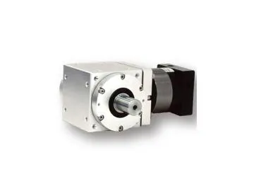 PAW-P Right Angle Speed Reducer
-
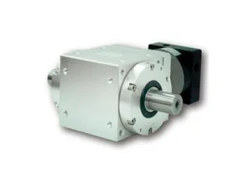 PAW-2P Right Angle Speed Reducer
-
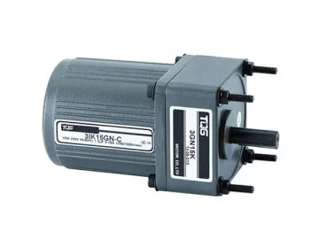 Micro AC Induction Gear Motor
-
 AAW-RFC Precision Right Angle Speed Reducer
-
 PT-C-K Steering Speed Reducer
-
 SZG-F Small Right Angle Gear Motor
-
 PT-2C-K Steering Speed Reducer
-
 ATM-2P Precision Steering Speed Reducer
-
 SZG-H Medium Right Angle Gear Motor
-
 Micro AC Variable Speed Gear Motor
-
 ATM-P Precision Steering Speed Reducer
-
 Micro AC Reversible Gear Motor
