Automatic Water Softener
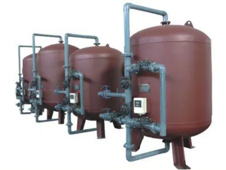
The JM series full-automatic multi-valve water softener is a revolutionary way to create softened water. This solution features a combination of hydraulic and pneumatic diaphragm valves with the innovative JM multi-valve controller. These improvements result in an updated product that surpasses existing soft water equipment that has been available for years. Invest in a soft water solution that's guaranteed to deliver.
Request a Quote ApplicationSoftened water is essential for many industrial and commercial uses. Boiler feed water, circulating water, heating and air conditioning make-up water, and other forms of production water can be effectively treated with this process. On average, anywhere from tens of tons to thousands of tons can be prepared by our automatic water softener.
Working principleWater hardness commonly consists of calcium (Ca2 ) and magnesium (Mg2 ) ions. Passing through the resin layer of the water softener, these hardness ions are exchanged, adsorbed and their concentration decreases. Simultaneously, sodium (Na ) ions are discharged into the water in equal measure. Ultimately, softened water devoid of hardness ions is produced.
When the resin has taken in a certain amount of calcium (Ca2 ) and magnesium (Mg2 ) ions, the regeneration process is activated to restore its softening and exchange capacity. This is done by washing the resin layer with salt water in a salt tank, and then releasing the hardness ions and regeneration waste liquid outside of the tank. This allows the resin to regain its original properties.
The multi-valve automatic water softener system is designed to allow for the smooth functioning of various processes associated with water softening services, utilizing different control diaphragms (e.g. hydraulic and pneumatic). Each valve is connected to the controller which follows a predetermined program to open and close the necessary passageways, allowing for easy running and regeneration. The system also contains resin and salt tanks, essential for completing the process.
| No. | Model | Production capacity | Control mode | Controller |
| 1 | JMT-750 | 8.0-10 | Single tank, timer control | JMA×1 |
| 2 | JMT-900 | 15-20 | ||
| 3 | JMT-1200 | 20-25 | ||
| 4 | JMT-1500 | 30-40 | ||
| 5 | JMT-1800 | 50-60 | ||
| 6 | JMT-2000 | 60-70 | ||
| 7 | JMQ-750 | 8.0-10 | Single tank, flow meter control | JMA×1 |
| 8 | JMQ-900 | 15-20 | ||
| 9 | JMQ-1200 | 20-25 | ||
| 10 | JMQ-1500 | 30-40 | ||
| 11 | JMQ-1800 | 50-60 | ||
| 12 | JMQ-2000 | 60-70 | ||
| 13 | JMD2-750 | 8-10 | Dual tank, single flow meter (one in service and one standby) | JMA×2 |
| 14 | JMD2-900 | 15-20 | ||
| 15 | JMD2-1200 | 20-25 | ||
| 16 | JMD2-1500 | 35-40 | ||
| 17 | JMD2-1800 | 50-60 | ||
| 18 | JMD2-2000 | 60-70 | ||
| 25 | JME2-750 | 16-20 | Dual tank, double flow meter (working simultaneously and regeneration consecutively) | JMA×2 |
| 26 | JME2-900 | 30-40 | ||
| 27 | JME2-1200 | 40-50 | ||
| 28 | JME2-1500 | 70-80 | ||
| 29 | JME2-1800 | 100-120 | ||
| 30 | JME2-2000 | 120-140 | ||
| 31 | JMD3-900 | 30-40 | Three tanks, single flow meter (two in service and one standby) | JMA×3 |
| 32 | JMD3-1200 | 40-50 | ||
| 33 | JMD3-1500 | 70-80 | ||
| 34 | JMD3-1800 | 100-120 | ||
| 35 | JMD3-2000 | 120-140 | ||
| 36 | JMD3-2500 | 200-250 | ||
| 37 | JMD3-3000 | 280-350 | ||
| 45 | JME3-900 | 45-60 | Three tanks, Three flow meters (working simultaneously and regeneration consecutively) | JMA×3 |
| 46 | JME3-1200 | 60-75 | ||
| 47 | JME3-1500 | 100-120 | ||
| 48 | JME3-1800 | 150-180 | ||
| 49 | JME3-2000 | 180-210 | ||
| 50 | JME3-2500 | 300-350 | ||
| 51 | JME3-3000 | 420-490 |
Notes: The selection of equipment is not limited to the above specifications. The multi-valve automatic soft water tank can be combined with larger tanks (such as five tanks). We can make special design according to the raw water analysis data and water requirements provided by customers. Equipment selection shall be determined as follows:
(1) counter-current regeneration or co-current regeneration;
(2) Flow control or set-timer.
Links:https://globefindpro.com/products/609.html
-
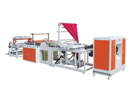 Automatic Coreless Bag on Roll Making Machine
-
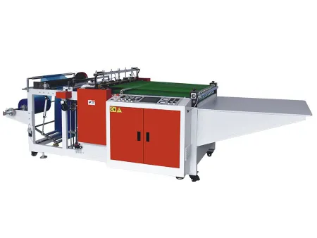 Heavy Duty Garbage Bag Making Machine
-
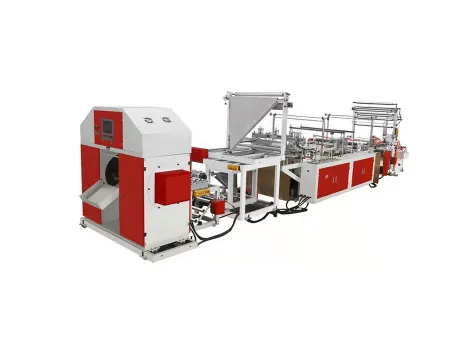 Automatic Ribbon-Through Garbage Bag Making Machine
-
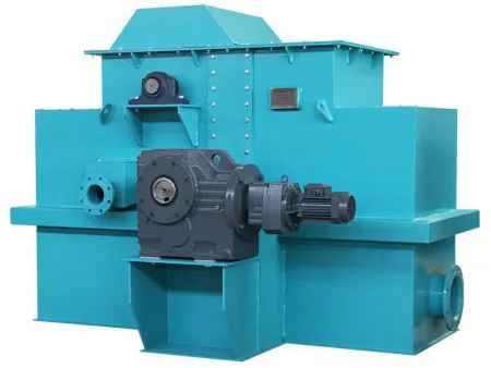 Magnetic Disk Separation and Purification System
-
 Electric Light Duty Truck
-
 Belt Filter Press, XYSD Series
-
 Garment Bag Making Machine
-
 Mini Type Blown Film Machine
-
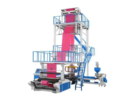 Three Layer Blown Film Machine
-
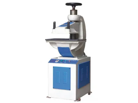 Hydraulic Punch Press
-
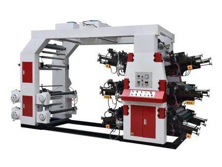 High Speed 4/6 Color Flexographic Printing Machine
-
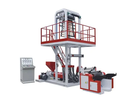 Single-layer Blown Film Machine

