Control and Display Device for Switchgear
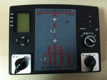
The control and display device for switchgear is a comprehensive, multifunctional, intelligent and dynamic indicating device for various kinds of 0.1-40.5kV indoor switch cabinets. With simplified panel and well-organized layout, this switchgear accessory provides information about switch status, and it has been widely utilized in electric power, chemical engineering, railway, mining, metallurgy, cement and other industries.
Function
1. Our switchgear operating and monitoring system offers an analog schematic of primary return circuit, covering many parameters, like handcart position, grounding knife switch status, energy storage status, etc.
2. This intelligent switchgear controller has an indicator to remind operators whether there is voltage on the high-voltage equipment at load side. This function can be expanded to HV equipment at busbar side, and phase comparison is also attainable.
3. Aside from abovementioned properties, the control and display device also offers other functions, including on-load locking, automatic heating/dehumidification, fault monitoring (for heater), real-time digital display of T and RH, overtemperature alarming (stop heating at the same time), intelligent misoperation warning (by audio), infrared induction of human, online temperature measurement at electrical contacts in switchgear, data transmission (RS485), etc.
Feature
1. All the major components are of industrial grade.
2. The switchgear operator adopts high-end PIC® Microcontroller supplied by Microchip Technology Inc.
3. Temperature data at high-voltage electrical contacts are transmitted in a wireless (2.4GHz) way, so this process is safe, reliable and anti-interference.
4. As for signal isolation, both discrete input and communication interface adopt optocoupler and switch, while 12V relay is adopted for the output.
5. The software makes use of several leading-edge technologies, such as redundancy, fault tolerance and digital filtering, to ensure its high reliability. So, our control and display device is able to work normally under extreme conditions for a long time.
Operating Condition
1. Normal working temperature: -20℃~ 65℃
2. Max. working temperature: -30℃~ 70℃
3. Storage temperature: -10℃~ 55℃
4. Ambient humidity: ≤95%
5. Atmospheric pressure: 80-110KPa
6. Altitude: ≤2500m
Ordering Instruction
The following information shall be provided when ordering this control and display device.
1. Schematic diagram
2. Product name, model and quantity
3. Power supply: AC/DC220V or AC/DC110V
4. Wiring length for temperature and humidity sensors
5. Temperature monitoring point
6. Other special requirements
Rear Terminals and Dimensions
MRD-CZX
Model:
Hole Size (220×165mm)
Temperature and Humidity
Sensing Module
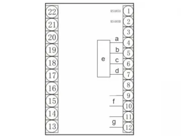
a - Potential Sensor Input for Phase A
b - Potential Sensor Input for Phase B
c - Potential Sensor Input for Phase C
d - Grounding
e - On-load Electromagnetic Locking Output (passive, normally closed)
f - Circuit Breaker (closed)
g - Circuit Breaker (open)
h - Testing Position
i - Working Position
j - Grounding Position
k - Energy Stored
l - Common Terminal
m - Lighting Output (passive, normally open)
n - Temperature and humidity sensor A
o - Temperature and humidity sensor B
p - Contact Temperature Receiving
q - AC/DC Input
r - Heater A Output (passive, normally open)
s - Heater B Output (passive, normally open)
t - Air Blast A Output (passive, normally open)
u - Air Blast B Output (passive, normally open)
v - Reactive Pulse
w - RS485 Output
x - Voltage
y - Current
Wireless Temperature Sensor
MRD-ZX
Model:
Hole Size (220×165mm)
Temperature and Humidity
Sensing Module
a - Potential Sensor Input for Phase A
b - Potential Sensor Input for Phase B
c - Potential Sensor Input for Phase C
d - Grounding
e - On-load Electromagnetic Locking Output (passive, normally closed)
f - Circuit Breaker (closed)
g - Circuit Breaker (open)
h - Testing Position
i - Working Position
j - Grounding Position
k - Energy Stored
l - Common Terminal
m - Lighting Output (passive, normally open)
n - Temperature and humidity sensor A
o - Temperature and humidity sensor B
p - DC/AC Input
q - Heater A Output (passive, normally open)
r - Heater B Output (passive, normally open)
s - Air Blast A Output (passive, normally open)
t - Air Blast B Output (passive, normally open)
u - RS485 Output
MRD-KX
Model:
Temperature and Humidity
Sensing Module
Hole Size (120×180mm)
Screw distance: 129×189mm
Diameter: M4
a - Circuit Breaker (closed)
b - Circuit Breaker (open)
c - Testing Position
d - Working Position
e - Grounding Position
f - Energy Stored
g - Common Terminal
h - On-load Electromagnetic Locking Output (passive, normally closed)
i - Potential Sensor Input for Phase A
j - Potential Sensor Input for Phase B
k - Potential Sensor Input for Phase C
l - Grounding
m - Heater A Output (passive, normally open)
n - Heater B Output (passive, normally open)
o - Air Blast Output (passive, normally open)
p - RS485 Output
q - Temperature and humidity sensor A
r - Temperature and humidity sensor B
s - AC/DC Input
t - Red
u - Black
v - Yellow
w - Green
Links:https://globefindpro.com/products/75631.html
-
 Wireless Temperature Monitoring System
-
 AGC30.20.012 Gearbox
-
 Rhyme of Light Series: 4 Leaf Sliding Door Fitting
-
 SBL40.00.07 Gearbox
-
 Arc Suppression Coil
-
 Temperature and Humidity Controller for Switchgear
-
 AGC65.14.021 Gearbox
-
 Cooler Control Cabinet for Transformer
-
 MRD-ZRK Monitoring Device for Neutral Grounding Resistor
-
 DH lock with Pull Handle 256: 4 Leaf Sliding Door Solution
-
 Modules of Reactive Power Compensation
-
 GGD Power Distribution Board
