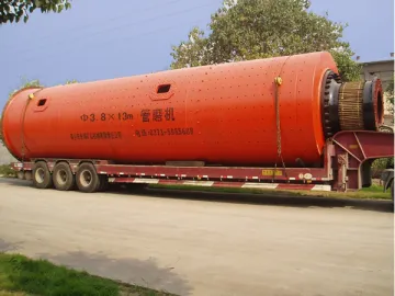
Coal-water Slurry Ball Mill
It is true that several milling processes can be used to produce coal-water slurry. But perhaps none are as suitable as the ball mill.
Coal-water slurry is mainly coal particles suspended in water, though other chemical admixtures are also added in proportion to the mix. Explosion-proof and readily flowable, the slurry is easy to store. Once vaporized, it can be used as a cheap, clean, and energy-efficient alternative to petroleum.
Below are some basic data related to the coal-water slurry produced by our ball mill.
Average Concentration: 66.31%
Average Particle Size: 37.06um
Percentage of Particles Finer than 75um: >80%
Productivity: 150t/h
Where to Use
Coal-fired power plant, cement plant, industrial boiler, fertilizer plant, refractory materials plant, refractory plant.
Parameters
Productivity: 150t/h
Installed Power: 630~1120kw
Ball Mill Working Principle
Working Principle
There is a girth gear bolted on the flange of grinding mill shell. Torque is transmitted to girth gear from the motor via the gearbox. The mill shell rotates under the action of this torque. There are grinding media in the mill body, which are raised to a height before falling back on the material to be ground during mill rotation. Coal, water and admixture are added to the mill at the feed end. After fine grinding, the slurry overflows from the mill body via the discharge end due to continuous feeding of new mixtures into the mill drum.
Structures
1. Modified gears are used for torque transmission at the gear ratio of 7.23:1. Maximum transmission stability is ensured.
2. Lube station ensures that the gearbox is well lubricated and effectively cooled. It makes for fast, trouble-free transmission.
3. The screw conveyor forces feedstock into the mill body without leakage. Parallel to feeding operation, water delivery and slurry re-feeding are carried out via the water pipes and slurry return pipes. This means the water, coal, and the slurry to be re-ground are fed to the mill body separately, which prevents any pipe from clogging due to the sticky coal-water mixture.
4. Both hydraulic supports under the mill shell are made of bracket, chassis and hydraulic jack. They prevent the cylinder from deforming while the mill comes to a halt.
Technical Specifications
| Specifications | Grinding Medium Diameter | Grinding Medium Length | Effective Volume | Rotational Speed | Weight ofGrinding Media | Drive Mode | Main Motor Power | Reference Weight | Note |
| m | mm | mm | m³ | r/min | t | kW | t | ||
| Φ3.2×4.5 | 3200 | 4500 | 33 | 15.5 | 56 | Side-Drive | 630 | 111.5 | Used in combination with other coal-water slurry equipment |
| Φ3.2×4.8 | 3200 | 4800 | 34 | 15.5 | 60 | Side-Drive | 710 | 121.2 | |
| Φ3.4×5.8 | 3400 | 5800 | 49 | 14.65 | 95 | Side-Drive | 900 | 160 | |
| Φ3.6×5.4 | 3600 | 5400 | 50 | 14.5 | 97 | Side-Drive | 1000 | 155 | |
| Φ3.6×5.8 | 3600 | 5800 | 53.8 | 14.3 | 135 | Side-Drive | 1120 | 175 | |
| Φ3.8×5.2 | 3800 | 5200 | 54.1 | 14.2 | 102 | Side-Drive | 1120 | 175 |
window.onload =function() {setItemByDivId('container','one|two|three|four|five|six|seven|eight','etw_link','color:fff; background:#cc0001;','color:#fff;background:#1e4ea7','setclass');doget('/loadByJs.php?type=loadByReg&page=/1-6-ball-mill-working-principle/158244&start=start&end=end','setresult');doget("/loadbyJs.php?type=bigCate&nums=6","etw_nav");}
Links:https://globefindpro.com/products/78176.html
-
 Wall Mounted Crane
-
 Single Girder Overhead Crane
-
 Pendant Control Station
-
 CT52507 52 Inch 5 Rattan Blade Ceiling Fan
-
 CT52508 52 Inch 5 Rattan Blade Ceiling Fan
-
 CT48301 48 Inch 3 Plastic Blade Ceiling Fan
-
 300,000 t/y Slag Powder Production Line
-
 4 Cubic Meter Vacuum Truck
-
 Vertical Roller Mill for GGBS
-
 12 Cubic Meter Fuel Tank Truck
-
 Vertical Roller Mill for Coal
-
 6 Cubic Meter Fuel Tank Truck
